background image

43

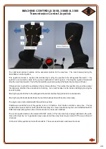
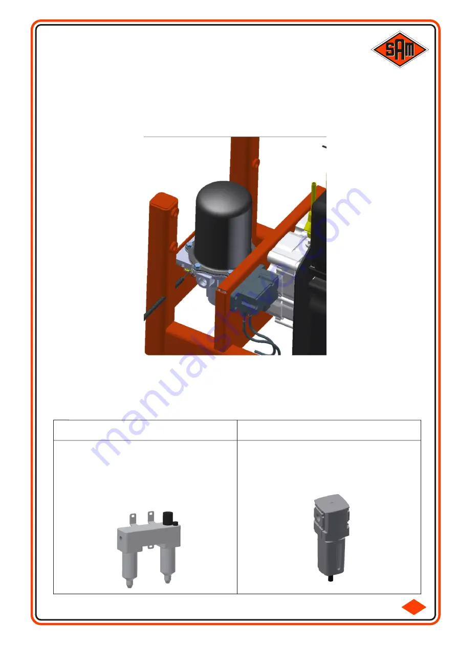
An air compressor mounted directly on the engine provides the air supply for the machine.

An Air Dryer with integral unloader valve is mounted on the Right hand side of the machine, behind the AdBlue 
Reservoir. This is preset to maintain the air pressure at approximately 8 bar (116 psi). A filter is incorporated 
within the unit and should be replaced following the maintenance schedule.
The Air reservoir, mounted below the engine, (incorporated within the chassis) should be drained daily.

COMPRESSED AIR SYSTEM

3-12

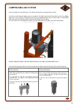
Air is fed throughout the machine via a filter/lubricator assembly located at the right hand end of the cat walk.

THE AIR RESERVOIR MUST BE CHECKED ANNUALLY BY A RECOGNISED INSPECTOR.

With lubricator

Without lubricator

SAM Ltd recommends the use of 'Tellus 37' lubricant in the 
lubricator bowl. 

It  is  impossible  for  SAM  Ltd  to  satisfactorily  adjust  the 
lubrication rate.   The operator must regulate this himself 
over several weeks.

Oil usage should be in the region of one bowl every 500 to 
600 hours.

Due to a recent product development, the system now 
does not require a lubricator as pneumatic components 
are now self lubricating.

In this case, the operator will find only a filter and water 
trap.

Summary of Contents for Horizon

Page 1: ...OPERATOR S MANUAL SANDS AGRICULTURAL MACHINERY Ltd Main Road Brunstead Stalham Norwich Norfolk NR12 9ER Tel 01692 580522 Fax 01692 580961 Email sales samltd co uk Website www samltd co uk Ver 4 8 2 ...

Page 2: ...ls thereafter CONDITIONS OF SUPPLY Sands Agricultural Machinery Ltd cannot be held responsible for injury or damage arising from incorrect handling usage or storage of this sprayer The Customer will become wholly responsible for items or build specifications outside our normal conditions of supply WARRANTY Sands Agricultural Machinery Ltd warrants all its products for a period of 1 year or 800 hou...

Page 3: ...verhead 2 2 3 Overhead Control Panel 2 2 4 Overhead Electronic Dash Display 2 2 5 Section 3 Mechanical Components Power unit 3 1 Steering Suspension Hydraulics 3 2 Auxiliary Spray Pack Hydraulics 3 3 Transmission Hydrostatic Pump 3 3 Transmission Hydrostatic Wheel Motor 3 4 Smart Drive Electronic Anti Slip System Optional 3 4 Suspension 3 4 Tyres General 3 5 Floatation Tyres 3 5 Tyres Customer Ope...

Page 4: ...7 Section 5 Spraying Filling The Spray Tank 5 1 Washing Out The Spray Tank 5 2 Pesticide Spraying The Environment 5 3 Pesticide Spraying Field Craft 5 4 Useful Publications Pesticide Use 5 4 Section 6 Maintenance 6 1 4000 4000E 5500 6000 Checks Service Intervals 6 1 1 2 Lubrication 6 1 2 Cab Clean Air Filter 6 1 3 Settings Specifications Ratings 6 1 4 Fuses Relays Over Head Right Hand Compartment ...

Page 5: ...4 SECTION 1 SAFETY ...

Page 6: ...d anti freeze should be pumped through the complete spraying system and or drain down 15 Before going onto the road check brakes lights indicators and tyre pressures Ensure 4WS is disengaged 4WS Indicators are extinguished on Over Head Control Panel and Vehicle is in Road Mode 16 Extra care should be taken when servicing the battery always isolate first The sulphuric acid contained within the batt...

Page 7: ... the sprayer are both safety critical services These systems should be thoroughly inspected at least every 250 hours and should coincide with the hydraulic filter changes The two braking systems fitted Primary and Parking require only a visual inspection around the wheel motors The multi disc parking brake fitted to each rear wheel motor should be inspected for back plate spring integrity and oil ...

Page 8: ...and Drugs It is extremely dangerous to operate machinery when under the influence of alcohol or drugs Do not consume alcoholic drinks or take drugs before or whilst operating the machine Be aware of medicines that can cause drowsiness or affect your ability to control the machine WARNING Clothing You can be injured if you do not wear the proper clothing Loose clothing can get caught in the machine...

Page 9: ...nger areas are the rotating shafts and belts on the engine the booms and anywhere beneath or behind the machine People can be killed or injured if these precautions are not taken WARNING Soft Ground Amachine can sink into soft ground Never work under a machine on soft ground WARNING Jacking Amachine can roll off jacks and crush you unless the wheels have been chocked Always chock the wheels at the...

Page 10: ...ntact your nearest fire department as quickly as possible Firefighters should use self contained breathing apparatus WARNING Modifications and Welding Non approved modifications can cause injury and damage Parts of the machine are made from cast iron welds on cast iron can weaken the structure and break Do not weld cast iron On no account weld or drill the chassis structure Contact SAM Ltd before ...

Page 11: ...ic components subjected to temperatures greater than 300C e g engine fire must be treated using the following safety procedure Make sure that heavy duty gloves and special safety glasses are worn Ensure that components have cooled then remove and place in plastic bags Thoroughly wash contaminated area with 10 calcium hydroxide or other suitable alkali solution if necessary use wire wool to remove ...

Page 12: ...u of possible hazards Do not over stretch or place yourself in dangerous positions to read the decals WARNING POWER LINES DANGER OF DEATH Stay away from power lines while folding booms In the unlikely event of any part of the machine touching a power line STAYIN THE CAB DON T PANIC TRYTO DRIVE CLEAR WARN OTHERS TO STAYWELLCLEAR If this is not possible or the machine catches fire JUMPWELLCLEAR DON ...

Page 13: ...lines 9 Don t put incomplete or incompatible chemicals in the same Tank mix check with your agronomist DO 1 Do study the chemical manufacturer s recommendations 2 Do check Nozzle output and pattern frequently 3 Do take adequate precautions when frost is expected 4 Do check forward speed at regular intervals 5 Do wear protective clothing THIS IS LAW 6 Do check for Boom overlap 7 Do check for correc...

Page 14: ...13 ...

Page 15: ...14 SECTION 2 MACHINE CONTROLS 2 1 4000 4000E 5500 6000 MACHINES 2 2 3000 3000E 3500 MACHINE ...

Page 16: ...he Steering Wheel tilts the Upper Section Direction Indicator Windscreen Wiper High Beams Horn Lower Column Adjustment tilts the Lower Section Left Indicator High Beams Ignition Engine Pre Heat Right Indicator Side Lights Low Beams Hazard Warning Ignition Key ...

Page 17: ... the maximum speed of 40kph is reached A 5500 sprayer automatically changes displacement until the maximum speed is reached If the joystick is returned to neutral the sprayer will stop The quicker the Joystick is moved the quicker the response whether it be acceleration or braking Care must be taken not to induce skidding by moving the Joystick too rapidly If greater braking is required than the j...

Page 18: ...e Boom section will fold OUT 1st fold Main Section 12m 2nd fold Mid Section 24m 3rd fold End Section 30 32 36m 4th fold Hydraulic Flip 24 28m 30 32m 36 40m 3rd fold when a 24m Independent Fold Boom is fitted Left Hand Independent 4th fold when a 24m Independent Fold Boom is fitted Right Hand Independent 4th fold when a 30 36m Independent Fold Boom is fitted Left Hand Independent 5th fold when a 30...

Page 19: ...l Ride Option Smart Drive Option Locked Smart Drive Option Unlocked Option C Front Single Spray Lines Front Rear Spray Lines Option Rear Spray Lines Option Spray Pump Speed 2 Spray Pump Speed 1 Option Boom Unlock 30m Tank Wash Boom Lock 30m Left Headland Nozzle Option Right Headland Nozzle Option Headland Lift Option Main Spray Tank Clean Water Tank Option D Smart Drive Option Locked Spray ON Opti...

Page 20: ...on 5500 Sprayers Set Decrease will SET the speed at which the Sprayer is travelling as the cruise speed Once set the speed can be increased or decreased by momentary operation of Reset or Set buttons approx 0 5km h each time Pressing the button again will decrease the vehicle speed by a predetermined amount Pressing the Brake Pedal or turning off Cruise Control will cancel Cruise Control Reset Inc...

Page 21: ...and Spray Boom Right Hand Headland Nozzle Controls the Headland Nozzle when fitted on the Right Hand Spray Boom Headland Lift Controls the Headland Lift when fitted when the Main Spray ON OFF is switched OFF the Spray Boom will automatically rise up When the Main Spray ON OFF is switch ON the Spray Boom will return to the previous spraying height Main Spray Tank Selects the Main ChemicalTank to sp...

Page 22: ...heat Function is active 10 Symbol indicatesAir Conditioning is active 11 Symbol indicates FullyAutomatic Mode is active 12 Bar display indicates actual Fan Speed during Manual Mode 13 Symbol indicates Fan Speed during Manual Mode 14 4 Digit 7 Segment display indicatingTemperature Value Error Code 15 Symbol indicates theTemperature Unit Celsius Fahrenheit 16 Symbol indicates the Operator Cabin 2 1 ...

Page 23: ... Automatically switch off after 10mins Rear Cab Working Lights Can be left on after switching Ignition off and will automatically switch off after 5mins or if Battery voltage drops below a set point to ensure the engine can still be started Automatically switch off in Road Mode Boom Rest Working Lights Boom Working Lights 4WS Engaged Indicators Illuminated when rear wheels are NOT straight Warning...

Page 24: ...Regeneration requests should not be ignored if delayed too long Deutz Engine warranty will be void Regeneration can be paused if required by pressing again Refer to Deutz Manual DPF Diesel Particulate Filter must be replaced Please contact SAM DPF Temperature Warning DPF is regenerating Engine Fault Read Fault Codes displayed at top of screen and contact SAM EAT Fault Read Fault Codes displayed at...

Page 25: ...may result LOW OIL PRESSURE STOP ENGINE 10 42 27 Setting the clock With the ignition on press and hole the top right hand two buttons until the display changes to RTC Setting Use the Up Down buttons to highlight the desired parameter to change Press the Centre button of the direction buttons to select the parameter Press the Up Down direction buttons to change the value to new value Press the Cent...

Page 26: ...e modes will not engage unless the front axle is straight or disengage unless the rear axle is straight Leakage within the steering system is corrected every time the rear axle disengages BEWARE There are a number of situations in which 4WS should NOT be used They are as follows 1 On side slopes when any crabbing will be amplified by the steering rear axle 2 When turning on steep hills where the r...

Page 27: ... Section is only to identify any differences in Cabin layout The main components are identified above and then explained in further details on the subsequent pages Steering Column 2 2 2 Armrest Controls 2 2 3 Joystick 2 2 4 Overhead Console 2 2 5 Section 2 2 MACHINE CONTROLS 3000 3000E 3500 Cabin 2 2 1 ...

Page 28: ...lumn are described in Section 6 2 of this manual The ignition key will start and stop the engine Warning light cluster Left Column top to bottom Battery Low fuel Suction filters Return filters Blank Second Column top to bottom Oil pressure Park brake Air filter Air pressure Blank but will illuminate for 2 secs with ign on Third Column top to bottom Turn beacon Fourth Column Main beam MACHINE CONTR...

Page 29: ...ives best overall performance 4 Steep downhill this mode provides the best control when descending a steep hill when traction is marginal If mode 3 is being used and the rear wheels begin to skip mode 4 may be selected on the move Remember if the machine will not climb the hill in Mode 3 never attempt to descend the hill The vehicle has a permanent four wheel drive system but this is only relevant...

Page 30: ...joystick further to the left against the detent enables the joystick to move backwards Moving the joystick backwards drives the machine backwards and the same rules apply The engine can only be started with the joystick in neutral Positioned around the face of the joystick is an arc of buttons Each button controls a spray line The top centre button represents the centre back frame spray line Seven...

Page 31: ...nes The left panel identifies the four switches which operate the front rear cab working lights the warning beacons and the boom working lights The right panel identifies the Rear camera screen which comes into operation when the ignition is on and the screen on off button is pressed MACHINE CONTROLS 3000 3000E 3500 Overhead console 2 2 5 ...

Page 32: ...31 SECTION 3 MECHANICAL COMPONENTS ...

Page 33: ... pump and diesel pump The smaller V belt drives the air conditioning compressor The condition and tension of these belts should be checked according to the maintenance schedule If a belt slips it becomes glazed and will fail to drive correctly even after it has been correctly re tensioned Should this occur then the belt and possibly the pulley will have to be replaced From the Left hand side of th...

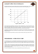
Page 34: ... engine RPM Maximum continuous working pressure must not exceed 170 Bar Any rear end equipment provided by the customer must be suitable for load sensing closed circuit use 3 2 The Transmission pump is mounted directly onto the flywheel end of the engine and turns at engine speed An electronic signal from the Joystick alters the angle of the swash plate inside the pump which in turn alters the str...

Page 35: ...lators fitted at each corner of the machine The accumulator pre charge has been set at the factory and needs no further adjustments The pre charge should be checked by a competent person every 2000 hours The rear axle is of the trailing arm type to reduce front end nodding For safety reasons it is not independent therefore the machine will always follow the attitude of the rear axle The front axle...

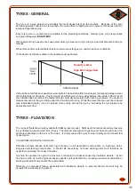
Page 36: ...rop sprayer are probably the most abused item on the machine Because of the ever decreasing weight nature of a crop sprayer the tyres attract a loading bonus however this bonus refers to low speed operations only Ensure tyre size i e contact area is suitable for the prevailing conditions Narrow tyres very steep slopes and green foliage just DO NOT MIX High loads and high speeds can cause premature...

Page 37: ...reduction in ability to traverse poor field conditions Driving Operation and Care The sprayer is designed to be filled on site with maximum load in the field with travel to and from the farm unladen Where this is not possible care must be taken to work within the parameters of the particular tyre option fitted Where maximum load is needed from farm to field a compromise in vehicle performance may ...

Page 38: ...ated at 1 6bar and 40kph Narrow tyres have a maximum capacity rated at 2 4 3 2 or 3 6bar and 40kph Latest technology Flexible sidewall tyres consult data sheets SAM or your tyre specialist Cleaning Wheels and Tyres If a TFR traffic film remover is used it must not be applied neat and must be diluted to the manufacturer s recommendations even so sometimes these can be quite harsh especially when us...

Page 39: ...mperature changes occur with operations at low pressure a daily check is advised Effects on pressure change by ambient temperature For example Atyre set at 15PSI at 15 C reduces in pressure to 13 4 at 0 C a 10 drop in inflation pressure Pressure CAUTION The pressurised air in the tyre is dangerous Explosive separation of a tire and rim parts can cause serious injury or death Do not attempt to moun...

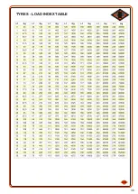
Page 40: ...39 3 8 TYRES LOAD INDEX TABLE ...

Page 41: ... is well supported A single jack under the centre of the axle is not acceptable Remove the four bolts in the bottom of the axle beam Remove the two track rod adjusting bolts In the bottom face of the axle beam are two slots and in each slot is a screwed stop screwed into the sliding leg If the stop is allowed to slide from one side of the slot to the other then the movement will be 6 152mm This eq...

Page 42: ...the front axle suspension plate is a hydraulic valve With the manual handle supplied raise the valve manual control fully up Start the engine and turn the steering wheel in the appropriate direction to slide the axles to the correct position at the fullest extent of the slot Note It is normal for only one axle leg to move at a time When the first leg moves to its fullest extent the second leg will...

Page 43: ... filters must be changed after the first 10 hours and thereafter every 250 hours or when the clogging indicator shows a blockage whichever comes first SAM LTD ONLYRECOMMENDS THE USE OF SAM SUCTIONAND RETURN FILTERS When changing oil filters always change the O Ring with the correct one supplied Asample of hydraulic oil should be analysed at the beginning of each season to ascertain as to whether t...

Page 44: ... AIR SYSTEM 3 12 Air is fed throughout the machine via a filter lubricator assembly located at the right hand end of the cat walk THEAIR RESERVOIR MUSTBE CHECKEDANNUALLYBYARECOGNISED INSPECTOR With lubricator Without lubricator SAM Ltd recommends the use of Tellus 37 lubricant in the lubricator bowl It is impossible for SAM Ltd to satisfactorily adjust the lubrication rate The operator must regula...

Page 45: ...44 ...

Page 46: ...45 SECTION 4 SPRAYING COMPONENTS ...

Page 47: ...and provides a visual indication of when the tank is nearing empty Because the float is located close to the center of the tank an extremely accurate reading of tank contents is provided at all times SIGHT GAUGE At the rear left hand corner of the sprayer are two rotary taps The tap labeled suction dictates where the spray pump will suck its water from This may be from the Main Spray Tank the Clea...

Page 48: ...400L min pump is available for applying higher rates on the 24m booms and is standard on all booms over this width Speed 1 gives an output of 275L min 375 RPM Speed 2 gives the full output from the pump The majority of conventional spraying may be carried out at the slower pump speed with a corresponding increase in pump life When self filling there will be little increase in the fill speed on spe...

Page 49: ...ndard Nozzle Body fitted to Horizon sprayers is the Hypro Duo React Twin Valve This body allows fitment of up to four nozzles in the forward nozzle position selectable by rotating the 4 way turret and a single in the rearward position This body allows for two different sizes of liquid fertiliser nozzles for a wider range of application rates operating each singly or both together The single rearwa...

Page 50: ... sections fully open loosen the hydraulic ram end and turn the ram shaft in the appropriate direction Tighten the ram end Adjustment should be made to the V G retaining chain if the boom is not horizontal when in the V G is in the fully lowered position This should take place according to the Maintenance Schedule BOOMS SHOULD NEVER BE FOLDED WHILE THE MACHINE IS MOVING It is extremely difficult to...

Page 51: ...he machine This ensures the boom will fold correctly especially if folding is taking place on a side slope The boom should be unlocked after unfolding prior to any spraying and locked prior to any folding The control for this function is fitted on the armrest It consists of 2 push button switches Indicator s within the switches will indicate the Boom Lock status Occasionally the boom lock will be ...

Page 52: ...oned at each corner of the spray pack lift the pack until the Tank Drain Tap and Clean WaterTank clear the chassis Drive forward slowly until the spray spreader pack is left free standing Remounting is the reverse of the above NOTE The support legs are not intended to take end thrust If the machine and the spray spreader pack are not correctly aligned when remounting damage could occur to the legs...

Page 53: ...52 SECTION 5 SPRAYING ...

Page 54: ... before attempting to spray WITH SELF FILLATTACHMENT 1 Connect the suction hose to the self fill inlet below the rotary taps The other end of the hose should be placed in to connected to a suitable water supply 2 Position the rotary Suction tap to Self Fill and the Pressure tap to Spray 3 With the engine running at 1000 rpm engage the spray pump but with all other controls in the off position 4 Wh...

Page 55: ...ray Nozzles or Both Forward Rearward Spray Nozzles depending on the nozzle body fitted to ensure all nozzles are washed Again increase the spray pressure manually to approx 4Bar great care should be taken not to over pressure the system When Tank Washing is complete reduce the spray pressure back to zero and switch off the Main On Off Spray Pump Boom Sections etc Performing Tank Wash from the oper...

Page 56: ... the watercourse Select products that are specific to the pest or weed to be controlled Consider not treating boom width or part of boom width closest to boundary SPRAYDRIFTis the most common culprit in reported incidents of pesticides misuse Drift is related to Spray quality Wind velocity at spray nozzle height Boom height Stability of local atmospheric conditions The following actions should be ...

Page 57: ...owing website address is the official HSE website for Pesticides It is recommended to visit and understand the information provided http www pesticides gov uk guidance industries pesticides The following publications are recommended as useful references in the field of pesticides use Health and Safety Executive Booklets Crop SprayingAS6 Poisonous Chemicals on the Farm HS G 2 Prevention ofAccidents...

Page 58: ...57 ...

Page 59: ...58 SECTION 6 6 1 MAINTENANCE 6 2 Fuses for 3000 3000E 3500 Machine ...

Page 60: ...heel Nut Torque Settings 340ft lbs 10200 Every 250 Hours Check Every 500 Hours or 12 Months Replace Every 1000 Hours Replace 12 Months Check Every 1500 Hours Check Every 2000 Hours Replace Request 24 Months Replace After 1st Days Work Check Daily Check Weekly Axles Bolts Track Rod Bolts Boom Alignment Main Fold Cylinder Lock Nuts Grease All Points excl Suction Pressure Taps Grease Suction Pressure...

Page 61: ...Check Every 1500 Hours Check Every 2000 Hours Replace Request 24 Months Replace After 1st Days Work Check Daily Check Weekly Boom Locks Power Unit Alternator Fan Belt Power Unit Air Conditioning Belt Hydraulic Oil Power Unit Coolant Cab Air Filter Wash Internal Filter Air System Lubricator Oil Dryer Filter Spray Nozzle Diaphrams 10545 1794 1L or Tellus 37 5865036 For FS only Not DR 01183382 011804...

Page 62: ...Retaining Grid it simply un clips from around the edges Remove the Dust Filter from the front of the Filter assembly and thoroughly clean it Swing out the Top Retaining Bar and then lift and remove the old Filter Dispose of contaminated filter responsibly Fit the new filter in place ensuring the handle and pleats face out ensuring the filter is located properly swing theTop Retaining Bar fully hom...

Page 63: ...Size metric 380 85 R34 3000 4000 420 85 R34 5500 6000 Tyre Size Imperial 14 9 x 34 16 9 x 34 E C E No H7 H7 H3 H1 Volts 12V 12V 12V 12V 12V 12V 12V 12V 12V 12V 12V Pressure Bar 2 0 2 0 Watts 55W 55W 35W 55W Pressure PSI 29 29 Bulbs Horizon 3000 4000 5500 6000 Tyre Pressures popular sizes pressures Tyre Size metric 600 60 R30 3000 VF600 60 R30 4000 VF600 60 R34 5500 6000 710 55 R30 5500 6000 Pressu...

Page 64: ...e used to lubricate Air system also see section on Air System ENGINE Please refer to the Deutz Operating Manual for lubrication information HYDRAULIC OIL Only a good quality hydraulic oil type HV46 that conforms to AFNOR NF 48600 or ISO 3448 CETOP RP 75 is suitable ANY OTHER GRADE OR SPECIFICATION OF OIL WILL CAUSE SERIOUS DAMAGE TO THE TRANSMISSION SYSTEM A Universal oil is NOT ACCEPTABLE SAM Ltd...

Page 65: ...STEERING COLUMN 5A PERM STOP BRAKE LIGHTS 5A UREA TANK 15A 4WS SENSOR 2A DIPPED BEAMS 10A DAY RUNNING LIGHTS 3A EGR 5A POCLAIN ECU 25A WIPERS 10A 4WS SENSORS 2A NOX SENSORS 15A ARM REST CONSOLE 5A HORN WASHERS 10A HORN 7 5A DEUTZ ENGINE ECU 30A PERM Electronic Dash 5A Rear Work Lights 30A Radio 7 5A Front Work Lights 30A Radio Perm 15A Beacons 15A Fans 30A Interior Light 5A Cool Box Cig Socket 20A...

Page 66: ...rtment 1 2 3 4 5 6 7 8 1 30AFUSE Eat System 2 RELAY Cab Supply Ignition 3 RELAY Rear End Supply Ignition 4 ConnectionTerminal Box 5 125AFUSE Cab Supply Ignition 6 125AFUSE Cab Supply Perm 7 125AFUSE Rear End Supply Ignition 8 Battery Isolator ...

Page 67: ...oss check relay fuse refer to page 51 If fuse blown investigate fix cause Booms will not fold unfold Boom Locks jammed Control relay or fuse fault Free Boom Locks clean readjust Control relay or fuse fault contact SAM Individual or group of rear end Hydraulics will not operate Control relay or fuse fault Control relay or fuse fault contact SAM Vehicle Horn Sounds without pressing button on Column ...

Page 68: ...e Inner Filter SPN 111 FMI 1 Low Coolant Level Check Repair Leaks Top up to correct Level If no Leaks found contact SAM Deutz SPN 3520 FMI 2 Add Blue Quality Low Drain Add Blue Tank refill with Deutz Specification Urea SPN 3520 FMI 2 Add Blue Quality Low Drain Add Blue Tank refill with Deutz Specification Urea SPN 524141 FMI 7 Engine Shut Off Demand Ignored This Error is usually accompanies anothe...

Page 69: ...l Filter 10192 2x Required 3 Power Unit Oil Filter 01183574 4 5 Hydraulic Oil Suction Filter 10200 6 Hydraulic Oil Return Filter 10201 7 Power Unit OuterAir Filter 04193517 8 Power Unit InnerAir Filter 02243946 9 Cab CleanAir Carbon Filter 10363 10 Air Dryer Filter 10379 11 Air Reservoir DrainTap 04910413 1 3 4 5 6 9 10 11 8 2 7 ...

Page 70: ...ure Filter 80 Mesh 21A63180 5 Self Fill Pipe Filter c w Non Return Valve 0825A369 6 Main FilterAssembly 317082 7 O Ring Main Filter 4900A519 8 Pressure FilterAssembly 20NF62550 9 O Ring Pressure Filter 21G10090 10 End Cap Snaplock 02200P20 11 HoseTail Snaplock 02200C20 12 End Cap Hiplock Z00CAP 13 HoseTail Hiplock 200C 1 3 4 5 6 8 2 10 12 13 7 9 11 ...

Page 71: ...let Nozzle Body complete 401255424510 7 3 4 Single Nozzle Body complete 402CR103 8 3 4 Quad Nozzle Body complete 4064757F 9 3 4 Quin Nozzle Body complete 4064957F 10 ISO Fan Cap Seal CP19438 EPR 11 Flow Stop Diaphragm 5865036 12 ISO Fan Cap CP25611 1 NY 13 End Cap Sprayline 01402909 14 Flow Stop c w Diaphragm 424510 15 3 4 Duo React Nozzle Body complete 42141503V 1 2 4 5 3 6 7 8 9 10 11 12 13 14 1...

Page 72: ...71 46 6 2 1 FUSES 3000 MACHINE ...

Page 73: ...URAL MACHINERY Ltd Main Road Brunstead Stalham Norwich Norfolk NR12 9ER Tel 01692 580522 Fax 01692 580961 Email sales samltd co uk Website www samltd co uk Specialist Suppliers of Agricultural Sprayers Service and Parts ...

Reviews: