3
Fabricator Instructions
Installation
5
3
/
4
"
(14.61)
8
3
/
4
"
(22.23)
5
1
/
2
"
(13.97)
4"
(10.16)
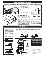
The open end of the fabricated
trough should include a flange
to match the flange on the
Trough Collector. The two
flanges are to be butted
together and securely welded.
At the closed end of the fabricated
trough, punch a 2” hole, centered
1-1/4” from the bottom of the trough.
This location ensures proper water
flow down the trough. The trough
should have a minimum depth of
3” at the closed end and a fall of at
least 3/32” per running foot to en-
sure adequate drainage to the unit.
FLANGE DIMENSIONS
TROUGH DETAILS
6
1
/
2
"
(16.51)
12
1
/
4
"
(31.11)
ø20"
(ø50.75)
Before installation it may be necessary to move the control from the back to
the front of the Trough Collector depending on orientation in the table. This
is easily accomplished using the existing fasteners, mounting holes and
wiring. If necessary, the control can be mounted remotely using an optional bracket.
Note: Additional field wiring is necessary for remote location of the control.
CONTROL
CONTROL
CONTROL
CONTROL
Weld the Trough Col-
lector top into the table
using these dimensions
for the table cut out.
Note: Before welding
confirm that there is a
minimum of 22” above
the Collector top for
basket removal.
Upon request, the Collector top may be shipped separately to a fabricator for welding to table.
ADJUSTABLE
LEGS
COLLECTOR
TANK
COLLECTOR
HARDWARE
COLLECTOR
TOP
Note: Before installation of
the Collector tank, the top
should be welded into the
table. Confirm that the top
has the pre-installed gasket
affixed before installation.
To install, raise the Collector
tank up to the Collector top that
has been welded into the table.
Using the supplied hardware,
attach the tank to the top. Ad-
just the legs by turning the foot
counter clockwise until they ex-
tend to the floor.
The design of the trough
may require that you rotate
the Collector tank in relation
to the top during installation.
The tank can be rotated
in 15 degree increments
to ease installation and to
keep the control square
with the front of the table.
15˚
90˚
180˚
15˚
90˚
180˚
15˚
90˚
180˚
TABLE CUT OUT DETAIL
1¼”
3” M
in.
Cen
ter H
ole
Trough


