Salus 091FLRF User Manual Download Page 4

2

GB

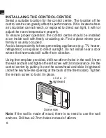
) of this manual before deciding on a final location for the receiver 

and control centre units. 

4) The Receiver should be mounted in a suitable location that is both 

accessible for the connection of mains and control wiring, and 

allows good reception of the RF signal. The Receiver needs a 230V 

AC mains supply to operate, and this should be fused appropriately 

(13A max.). The Receiver should be 

mounted in a location where it will 

not  come  into  contact  with  water, 

moisture or condensation.

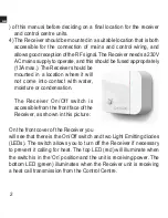
   The  Receiver  On/Off  switch  is 

accessible from the front face of the 

Receiver, as shown in this picture:

On the front cover of the Receiver you 

will see that there is the On/Off switch and two Light Emitting diodes 

(LEDs). The switch allows you to turn off the Receiver if necessary 

to prevent it calling for heat. The top LED (red) will illuminate when 

the switch is in the ‘On’ position and the unit is receiving power. The 

bottom LED (green) illuminates when the Receiver unit is receiving 

a heat call transmission from the Control Centre.

Summary of Contents for 091FLRF

Page 1: ...Programmable Room Thermostat with RF Volt Free Model 091FLRF User s Manual...

Page 2: ......

Page 3: ...inked by Radio Frequency The Receiver is easily installed using the Industry Standard back plate supplied for mounting purposes only as no wiring is required when installing the control centre The bac...

Page 4: ...ation where it will not come into contact with water moisture or condensation The Receiver On Off switch is accessible from the front face of the Receiver as shown in this picture On the front cover o...

Page 5: ...3 GB The wiring terminals and RFAddress Code setting DIP switches are located on the rear of the Receiver as shown in this picture...

Page 6: ...Install each unit following the TESTING THE RF TRANSMISSION section of this manual Once you are happy with the operation of one unit you may install the next Once all Receiver s are installed if one u...

Page 7: ...issions with the same address code setting as its own address code 1 To adjust address code of Receiver Control Centre simply push up or down on the 5 dip switch levers The leavers are numbered 1 to 5...

Page 8: ...6 GB Factory Defaut Setting Dip switch 1 5 in On position 1 2 3 4 5 ON Address Code Dip Switch Leavers 1 2 3 4 5 ON...

Page 9: ...l the set point temperature is higher than room temperature by a few degrees 2 Wait for a few seconds The animated fun heat call indicator should appear on the bottom right of the LCD on the control c...

Page 10: ...ied Avoid close proximity to heat generating appliances e g TV heater refrigerator or exposed to direct sunlight Do not install near a door where the thermostat will suffer from vibration Using the te...

Page 11: ...for the replacement of batteries After opening the door you can flip the door up or down to see the battery compartment The control centre is operated by two AA alkaline batteries Please remove the f...

Page 12: ...cuit and damage the control centre LCD 1 Day of the week Indicator 2 Time 3 Temperature 4 Program Number 5 Program Profile Indicator 6 Frost Protection 7 Manual Override Indicator 8 Output On Indicato...

Page 13: ...grammable thermostat It can automatically adjust the room temperature to a comfortable level when you are at home and lower it to save energy when you go out or sleep What you have to do is to program...

Page 14: ...e Buttons used Example When start or after reset the time is 00 00 Sunday To set the clock to current time e g 11 23 Tuesday press d for day h for hour and m for Note When you press and hold the keys...

Page 15: ...ng of the current temperature mode or which will be flashing Press or to review or change the temperature Press OK to directly return to normal operation mode Buttons used Example I In normal mode II...

Page 16: ...C Continue to pressing until the desired setting comes III The setting will change rapidly by pressing and holding the keys IV Please note the temperature mode indicator A means the comfort temperatur...

Page 17: ...program comes Press OK to clear override Buttons used Example I In normal operation mode press to change the current comfort setting to economy setting The temperature is now set to economy mode This...

Page 18: ...ram When timer hold is active pressing the corresponding temperature mode key e g if comfort mode is being held will show the remaining hold time The remaining hold time can also be changed by using t...

Page 19: ...s You can use or to change the distribution of comfort or economy temperature and h to review the setting Press OK to return to normal operation mode Buttons used There are altogether nine programs av...

Page 20: ...0 6 12 18 24 PROG 0 0 6 12 18 24 PROG 1 0 6 12 18 24 PROG 2 0 6 12 18 24 PROG 3 0 6 12 18 24 PROG 4 0 6 12 18 24 PROG 5 0 6 12 18 24 PROG 6 0 6 12 18 24 PROG 7 0 6 12 18 24 PROG 8 Program 0 is a spec...

Page 21: ...et the time shown to economy temperature by pressing or press to set it to comfort temperature Or you can use h key to pass through the time without changing the setting Since we want to set 13 00 to...

Page 22: ...on mode Note I Program 0 1 2 3 4 5 are preset programs and cannot be used to edit them But the h key is still active II The nine programs are common to all seven days This includes the three user defi...

Page 23: ...s All seven days set to PROG 1 User define programs Set to comfort Manual override All cleared Output Off Heat mode Delay off Span 1 C Note Do not use a pencil to push the reset button because the gra...

Page 24: ...for a heating system the comfort temperature is higher than the economy temperature while it is reverse for a cooling system Delay On press OK to confirm Delay On mode or press Comfort or Econmic the...

Page 25: ...table Span Heating System Cooling System 0 5 C On when Tr Ts 0 2 Tr Ts 0 2 Off when Tr Ts 0 2 Tr Ts 0 2 1 C On when Tr Ts 0 4 Tr Ts 0 4 Off when Tr Ts 0 4 Tr Ts 0 4 Ts Set temperature Tr Room tempera...

Page 26: ...the system when the room temperature is higher than the set temperature 3 There is no more defrost temperature The snow and 7 C will not be displayed If you select pro gram 0 the thermostat will swit...

Page 27: ...tions 20 C 60 C to 90 RH non condensing Frost Protection Temperature 7 C Temperature Control Accuracy 0 5 C at 25 C Operating Humidity 0 to 90 RH non condensing Time Display 24 hour Clock Accuracy 70s...

Page 28: ......

Page 29: ......

Page 30: ......

Reviews: