background image

All contents current at time of publication.
SALTO Systems S.L. reserves the right to change availability of any
item in this catalog, its design, construction, and/or materials.

©

2020 SALTO Systems S.L.

226079-ED2.- 12/02/2021

XS4 Controller

Installation guide

UBOX4000

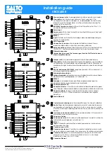
The LEDs in the top layer of the CU show the state of the system:

LED name

Description

ON

GREEN ON: the unit is powered correctly
BLINKING RED: the unit is not powered properly (check power supply)
BLINKING ORANGE: addressing mode
OFF: not powered

BUS485

ON UBOX4000: To be defined

OFF UBOX4000: To be defined

TAMPER

ON: tamper alarm active
OFF: tamper alarm not active

IN1-IN6

ON: active input (depends on the input type configured in the software)
OFF: inactive input (depends on the input type configured in the software)

READER

ON: the reader is communicating with the CU
OFF: the reader is not communicating with the CU (press the CLR to start detection process)

RL1-RL4

ON: the relay is activated (NO is connected with C).
OFF: the relay is inactive (NC is connected with C).

Signaling:

Los LEDs en la parte superior de la CU muestran el estado del sistema:

Nombre del LED

Descripcióon

ON

VERDE ON: el dispositivo está correctamente alimentado
ROJO INTERMITENTE: el dispositivo no está correctamente alimentado (comprobar la fuente de alimentación)
NARANJA INTERMITENTE: modo direccionamiento
OFF: sin alimentación

BUS485

ON UBOX4000: Por definir.

OFF UBOX4000: Por definir.

TAMPER

ON: alarma tamper activada
OFF: alarma tamper desactivada

IN1-IN6

ON: input activado (depende del tipo de input configurado a través del software)
OFF: input desactivado (depende del tipo de input configurado a través del software)

READER

ON: el lector comunica con la CU
OFF: el lector no comunica con la CU (presione el botón CLR para iniciar la detección)

RL1-RL4

ON: relé activado (NO está conectado con C).
OFF: relé desactivado (NC está conectado con C).

Señalética:

E

Eng

F

Les LEDS en façade avant de la CU indique l'état du système

Nom LED

Description

ON

VERT : l'appareil est correctement alimenté
Rouge clignotant : l'appareil est mal alimenté (vérifier la tension d'alimentation)
Orange clignotant : en mode adressage
OFF: non alimenté

BUS485

ON UBOX4000 : À définir.

OFF UBOX4000 : À définir.

TAMPER

ON : alarme active
OFF : alarme désactivé

IN1-IN6

ON : entrée active (dépend du type d'entrée configuré dans le logiciel)
OFF : entrée inactive (dépend du type d'entrée configuré dans le logiciel)

READER

ON : le lecteur est en communication avec la CU
OFF : le lecteur ne communique pas avec la CU (appuyez sur le CLR pour lancer le processus de détection)

RL1-RL4

ON : le relais est actif (NO est connecté avec C)
OFF : le relais est inactif (NC est relié à C)

Signalisation:

9/18

Summary of Contents for UBOX4000

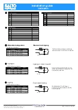
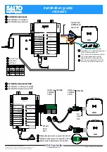
Page 1: ...VDC Input A B 12VDC Output 1A Power Input 12V DC 1A GND GND A B Model CU42E0 104 4 1 8 121 4 3 4 43 1 11 16 10 3 8 44 1 3 4 131 5 3 16 4 5 32 UBOX42DxxG UBOX42DxxT Model CU42xx UBOX 4000 MODEL CU42E0...

Page 2: ...e a la entrada de alimentaci n protegida por un fusible de 1 A BUS485 Entradas el instalador ha de identificar el cable para el puente dependiendo de la configuraci n de la entrada Conexi n para el PP...

Page 3: ...el Software 1k recomendado 1k5 2k2 3k3 4k7 6k8 10k Connexion d entr e Connexion d entr e supervis e CUADAPT ou lecteur tiers IN3 IN4 IN5 IN6 Sortie D0 Sortie D1 Sortie D0 Sortie D1 Sortie Clock Sortie...

Page 4: ...e La CU elle seule consome 400mA D pendant de l installataion l installateur doit calculer l alimentation n cessaire Note 2 M me tension que l entr e Note 3 R sistance de pull up 1K Note 4 Consultez l...

Page 5: ...EADER 2 RL1 RL2 RL3 RL4 C NC NO C NC NO C NC NO C NC NO BUS485 Ethernet 10Base T 100Base TX ON 12VDC Input A B 12VDC Output 1A Power Input 12VDC 1A GND GND A B Model CU42E0 Model CU42xx UBOX 4000 MODE...

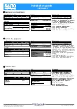
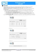
Page 6: ...er guide assign the IP address to the UBOX4000 3 Adress the CU42E0 3 1 Press the CLR BUTTON CU42E0 to detect the readers Check that the reader s LEDs blink and the BUS485 LEDs are switched ON 3 2 The...

Page 7: ...manual de usuario de usuario de SALTRO ProAccess SPACE 3 Direccionar la UBOX4000 3 1 Pulsaci n corta del CLR para detectar los lectores Comprobar que los LEDs de los lectores y el BUS485 est n encendi...

Page 8: ...Adresser la UBOX4000 3 1 Appuyer sur la touche CLR pour d tecter les lecteurs V rifier que les voyants des lecteurs clignotent et que les voyants du BUS485 sont allum s 3 2 Le UBOX4000 est un appareil...

Page 9: ...o no est correctamente alimentado comprobar la fuente de alimentaci n NARANJA INTERMITENTE modo direccionamiento OFF sin alimentaci n BUS485 ON UBOX4000 Por definir OFF UBOX4000 Por definir TAMPER ON...

Page 10: ...C NC NO C NC NO BUS485 Ethernet 10Base T 100Base TX ON 12VDC Input A B 12VDC Output 1A Power Input 12V DC 1A GND GND A B Model CU42E0 104 4 1 8 121 4 3 4 43 1 11 16 10 3 8 44 1 3 4 131 5 3 16 4 32 Mo...

Page 11: ...er input poort beschermd door een 1A zekering BUS485 Ingangen Installateur moet vaststellen welke kabel nodig is afhankelijk van de input configuratie Indien geen deursensoren of sabotagecon tact gebr...

Page 12: ...ng Data Ausgang TX Ausgang TX Ausgang Wiegand Omron RS232 Die Widerst ndswert k nnen via Software definiert werden 1k5 2k2 3k3 4k7 6k8 10k Ingangen Ingangen onder toezicht CUADAP en lezers van derden...

Page 13: ...Schwarz Zwart Svart 2 1 READER_2 READER_1 READER_2 READER_1 Gleiches Paar Hetzelfde paar Samma par B A Mindestabstand zwischen Lesern 20in 50 cm Minimale afstand tussen de lezers 20in 50 cm Minsta avs...

Page 14: ...gebruik wordt gemaakt van de 12 V uitgang De controller alleen verbruikt 400mA Afhankelijk van de aangesloten componenten moet de installateur een geschikte voeding berekenen en plaatsen Opm 2 Evenve...

Page 15: ...aster einmal kurz wenn der Sabotagekontakt offen ist Die LED s m ssen einmal kurz aufleuchten 3 2 CU42E0 ist DHCP Vorbereitet In Werksauslieferung ist der DHCP Modus aktiviert Wenn der Kunde keinen DH...

Page 16: ...tellingen en ken het IP adres toe aan de CU42E0 in de software 3 Adresseer de CU42E0 3 1 Klik de CLR knop kort in om de aangesloten lezers te detecteren controleer of de oranje led op de lezers geknip...

Page 17: ...er St ll in dip switcharna f r alla CU4200 och tilldela IP adress till CU42E0 3 Adressera CU42E0 3 1 Tryck p CLR knappen CU42E0 f r att detektera l sarna och den anslutna CU4200 Kontrollera att l sarn...

Page 18: ...De controller is juist gevoed KNIPPEREND ROOD De controller is niet juist gevoed controleer de voeding KNIPPEREND ORANJE adressering modus UIT Geen voeding BUS485 AAN op UBOX4000 Worden gedefinieerd U...

Reviews: