salmson MINI SUBSON Installation And Operating Instructions Manual Download Page 11

ENGLISH

11

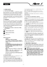
WARNING! Risk of fatal injury!
The pump may not be used to empty swimming pools /
garden ponds or similar locations if there are people in
the water.

WARNING! Health risk!
Owing to the materials used, the pumps are not suitable
for drinking water! Polluted waste water presents a
health risk. 

CAUTION! Danger of material damage!
Pumping materials which are not approved can lead to
damage to the product. 

The pumps are not suitable for water containing coarse
impurities such as sand, fibres or faeces, flammable liq-
uids or for use in areas at risk of explosion.

5. DETAILS ABOUT THE PRODUCT

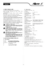
5.1 Type key      


5.3 Scope of delivery 

Every pump is delivered with

•5 or 10 m connection cable,

•a mains power plug,

•connected float switch („MINI SUBSON MF...“),

•hose connection (in steps Ø 20, 25 mm, R1“),

•coupling (Rp 1 / Rp 1¼) with integrated non-return valve,

•installation and operating instructions.

5.4 Accessories

Accessories must be ordered separately (see catalogue)

6. DESCRIPTION AND FUNCTION

6.1 Description of the pump (See FIG. 2)     

The pump can be completely immersed in the liquid to be
pumped. The pump housing is made of plastic. The electric
motor is protected from the pump cavity by a shaft seal ring
sealing the oil cavity and by a mechanical seal which seals the
oil cavity from the water. To ensure that the mechanical seal is
always lubricated and cooled, even when running dry, the
mechanical seal chamber is filled with oil.

The motor is cooled by the surrounding fluid.

The motor is equipped with integrated motor protection, which
switches off on overload and automatically switches on again
after cooling down.

The pump is installed on the base of a shaft. When in a fixed
installation it is screwed to a fixed pressure line. For a mobile
installation it is connected to a hose.

The pump is operated by plugging in the power supply plug.

If the waste water line does not allow any interruptions, then a
2nd pump (automatic standby pump) in conjunction with the
necessary switchgear (accessories) increases the reliability in
case of a fault with the 1st pump.

6.2 The pump functions

Pump with a float switch: 

The  „MINI SUBSON MF...“ 

(See FIG. 1)

 pumps work automati-

cally in that a float switch turns the pump on, via the free cable
length, once the water reaches a certain level and turns it off
again when it reaches a minimum water level. Level suction to
5 mm (See FIG. 1).

Pump without a float switch: 

The versions without a float switch are suitable for use with
external switching, for example using switchgear (accessories).

Example

: MINI SUBSON M, MINI SUBSON MF

MINI SUBSON MP, MINI SUBSON MFP

MINI SUBSON

: submersible pumps 

M

: single-phase (monophasé)

F

: with float switch

P

: portable version (10 m cable) 

5.2 Technical data

max. permissible grain 
size

: 3  mm

supply voltage

: 1~ 230 V, ± 10 %, 

supply frequency

: 50 Hz

protection class

: IP 68

speed

: max. 2900 ¹/min (50 Hz)

max. current consump-
tion

: 0,8 A

power consumption P

1

: 0,18  kW

nominal motor power P

2

: 0,1 kW

max. flow rate

: see name plate

max. head of water

: see name plate

operating mode S1

: 200 hours of operation per year

operating mode S3 
(optimum)

: intermittent duty, 25 % (2.5 min. 

operation, 7.5 min. pause)

recommended switch-
ing frequency

: 20  times/h

max. starts per hour

: 50 times/h

nominal diameter of the 
pressure port

: 25  mm

permissible temperature 
range of the pumped 
liquid

: +3 to 35°C

max. immersion depth

: 5 m

level suction to

: 5 mm

noise level at min. level

: < 57 db(A)

Pos.

Description of component

1

housing

2

stator (winding)

3

handle

4

sheet  metal  screw

5

O-ring

6

sheet  metal  screw

7

radial shaft sealing ring

8

mechanical seal

9

O-ring

10

cover plate

11

seal housing

12

screw

13

seal

14

O-ring

15

shaft seal ring

16

O-ring

17

pump housing

18

spacing ring

19

impeller

20

suction basket

21

washer

22

spring washer

23

nut

25

connection cable

26

hose nozzle Ø 20, 25 mm

27

seal

28

float switch

29

coupling

30

non-return valve

31

fixing for non-return valve

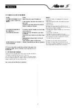
Summary of Contents for MINI SUBSON

Page 1: ...MISE EN SERVICE INSTALLATION AND OPERATING INSTRUCTIONS INSTRUCCIONES DE INSTALACIÓN Y FUNCIONAMIENTO ISTRUZIONI DI MONTAGGIO USO E MANUTENZIONE FRANCAIS ENGLISH ESPAÑOL ITALIANO N M S STOCK N 2 069 500 Ed 01 10 06 MINI SUBSON ...

Page 2: ...2 ...

Page 3: ...ngsdirektiv 73 23 EWG med fšljande Šndringar elektromagnetisk kompatibilitet 89 336 CEE författningar om byggprodukter 89 106 CEE Det överensstämmer även med följande harmoniserade europeiska standarder som nämnts på den föregående sidan ýESKY PROHLÁŠENÍ O SHODċ Spoleþnost Pompes SALMSON prohlašuje že výrobky uvedené v tomto prohlášení odpovídají ustanovením níže uvedených smČrnic a národním právn...

Page 4: ...4 FIG 1 FIG 2 Hmin 219 Ø 155 1 Ø 25 35 80 Ø 20 Hmin 219 Ø 155 1 Ø 25 35 5mm Ø 20 Rp 1 1 4 Rp 1 R 1 Ø 20 Ø 25 29 1 8 12 13 14 18 15 23 21 22 19 5 4 17 20 25 28 27 26 11 10 9 7 6 3 16 2 30 31 ...

Page 5: ...t être les suivants défaillance de fonctions importantes de la pompe ou de l ins tallation défaillance du processus d entretien et de réparation prescrit dangers pour les personnes par influences électriques méca niques ou bactériologiques dommages matériels 2 4 Consignes de sécurité pour l utilisateur Il convient d observer les consignes en vue d exclure tout ris que d accident Il y a également l...

Page 6: ...onte nant des impuretés grossières telles que sable fibres ou matières fécales de même elles ne doivent pas être utilisées pour refouler des liquides combustibles ou implantées dans des zones soumises à un risque d explosion 5 CARACTÉRISTIQUES DU PRODUIT 5 1 Dénomination 5 3 Etendue de la fourniture Les pompes sont livrées avec un câble 5 ou 10 m suivant la pompe et équipé d une prise de contact u...

Page 7: ...TTENTION Risques de dommages matériels Risques de dommages en cas de manipulation incor recte La pompe doit uniquement être suspendue à un câble ou à une chaîne via la poignée jamais au niveau du câble électrique du flotteur ou du raccord pour flexi ble tuyau Le lieu d implantation de la pompe et la cuve doivent être à l abri du gel La dimension de la cuve doit impérativement garantir la mobi lité...

Page 8: ... pompe L air entraîné peut empêcher l amorçage de la pompe La quantité d eau maximale pouvant entrer dans la cuve ne peut dépasser le débit de la pompe Observer la cuve durant la mise en service 9 ENTRETIEN AVERTISSEMENT Risque d électrocution Il convient d exclure tout danger lié à l énergie électri que Lors des travaux d entretien et de réparation mettre la pompe hors tension et la verrouiller c...

Page 9: ...é trop élevée Laisser refroidir Pompe ensablée ou bloquée Débrancher la pompe et la sortir de la cuve Démonter la crépine d aspiration et rincer la cré pine la roue à l eau courante LA POMPE NE DÉMARRE PAS NE S ARRÊTE PAS Contacteur à flotteur bloqué ou entravé dans ses mouvements Contrôler le contacteur à flotteur et s assurer de sa mobilité LA POMPE NE REFOULE PAS L air présent dans l installati...

Page 10: ...ences Property damage 2 4 Safety instructions for the operator The existing directives for accident prevention must be adhered to Danger from electrical current must be eliminated Local directives or general directives e g IEC VDE etc and local power supply companies must be adhered to 2 5 Safety instructions for inspection and installation work The operator must ensure that all inspection and ins...

Page 11: ... the waste water line does not allow any interruptions then a 2nd pump automatic standby pump in conjunction with the necessary switchgear accessories increases the reliability in case of a fault with the 1st pump 6 2 The pump functions Pump with a float switch The MINI SUBSON MF See FIG 1 pumps work automati cally in that a float switch turns the pump on via the free cable length once the water r...

Page 12: ...device RCD with a trip current of 30 mA this is manda tory when used outdoors To connect the pump to switchgear the power supply plug has to be cut off and the connection cable then has to be wired as follows The power socket or switchgear must be installed in a dry space that can not be flooded 8 COMMISSIONING CAUTION Risk of damage to the pump The pump must not run dry Running dry shortens the l...

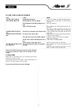
Page 13: ...mp is silted up or seized Remove power from the pump and pull it out of the shaft Remove the suction basket and wash down the suction basket and impeller under running water THE PUMP DOESN T TURN ON OFF Float switch is jammed or cannot move freely Check the float switch and make sure that it can move freely THE PUMP DOESN T PUMP PROP ERLY Air in the system can t escape Bleed air from the system em...

Page 14: ... por los daños sufri dos Si no se siguen las instrucciones se pueden producir entre otros los siguientes daños Fallos en funciones importantes de la bomba o el sistema Fallos en los procedimientos obligatorios de mantenimiento y reparación Lesiones personales debidas a causas eléctricas mecánicas o bacteriológicas Daños materiales 2 4 Instrucciones de seguridad para el operador Deberán cumplirse l...

Page 15: ...s grandes como arena fibras o heces tam poco para líquidos inflamables ni para la aplicación en zonas con riesgo de explosión 5 INDICACIONES SOBRE EL PRODUCTO 5 1 Claves del tipo 5 3 Suministro Cada bomba se suministra con cable de alimentación de 5 o 10 m enchufe con toma de tierra interruptor de flotador conectado MINI SUBSON MF conexión de manguera gradual Ø 20 25 mm R1 acoplamiento Rp 1 Rp 1 c...

Page 16: ... en la bomba a causa de un manejo indebido Debe colgarse la bomba con ayuda de una cadena o de una cuerda sólo por el asa nunca se debe emplear un cable eléctrico del flotador o una conexión de tubo manguera El lugar de instalación y el pozo para la bomba deben estar libres de óxido Es imprescindible que la naturaleza del pozo garantice el movimiento libre del interruptor de flotador MINI SUBSON M...

Page 17: ...de agua que fluye al pozo no debe sobrepasar la potencia de impulsión de la bomba Debe observarse el pozo durante la puesta en marcha 9 MANTENIMIENTO ADVERTENCIA Peligro por tensión eléctrica Es preciso excluir la posibilidad de que se produzcan peligros debidos a la energía eléctrica Antes de realizar trabajos de mantenimiento o repara ción desconecte la bomba y protéjala contra conexiones por pa...

Page 18: ...ar enfriar Bomba llena de arena o bloqueada Desconectar la bomba de la red y sacar del pozo Desmontar la alcachofa enjuagar la alcachofa el rodete bajo el grifo LA BOMBA NO SE CONECTA DESCONECTA El interruptor de flotador está bloqueado o no se mueve libremente Comprobar el interruptor de flotador y garanti zar su movilidad LA BOMBA NO BOMBEA El aire de la instalación no puede salir Purgar o si es...

Page 19: ...materia di prevenzione degli infortuni sul lavoro Prevenire qualsiasi rischio derivante dall energia elettrica Applicare e rispettare tutte le normative locali e generali ad esempio IEC ecc e le prescrizioni delle aziende elettriche locali 2 5 Prescrizioni di sicurezza per il montaggio e l ispezione Il gestore deve assicurare che le operazioni di montaggio e ispezione siano eseguite da personale a...

Page 20: ...a tenuta meccanica in caso di funzionamento a secco la camera della tenuta meccanica è riempita di olio Il motore viene raffreddato dal fluido movimentato circolante Il motore è provvisto di un salvamotore integrato che in caso di eccessivo riscaldamento disattiva automaticamente il motore e lo riattiva dopo il raffreddamento La pompa viene collocata sul fondo di un pozzetto In caso di installazio...

Page 21: ...lico predisporre un sifone sulla tubazione di mandata Tale sifone deve essere posizionato a un livello supe riore rispetto al livello del canale fognario solitamente livello stradale Raccordo per flessibili il manicotto flessibile consente il colle gamento a un tubo flessibile Ø 20 oppure 25 mm Eventual mente adattare il diametro del manicotto flessibile al diametro del tubo flessibile ritagliando...

Page 22: ... essere sostituite adottando ricambi originali 8 Rimontare la pompa osservando la sequenza inversa 10 GUASTI CAUSE E RIMEDI Quando nonostante tutto non si è in grado di eliminare la causa della guasto rivolgersi a una ditta specializzata oppure al rappresentante o al Centro Assistenza Salmson più vicino 11 PARTI DI RICAMBIO Le parti di ricambio possono essere ordinate presso la ditta specializzata...

Page 23: ...NOTES 23 ...

Page 24: ...L 39 059 280 380 FAX 39 059 280 200 info tecniche salmson it W S L LEBANON Bou Khater building Mazda Center Jal El Dib Highway PO Box 90 281 Djeideh El Metn 1202 2030 Beiruth LEBANON TEL 961 4 722 280 FAX 961 4 722 285 wsl cyberia net lb SALMSON ARGENTINA S A Av Montes de Oca 1771 75 C1270AABE Ciudad Autonoma de Buenos Aires ARGENTINA TEL 54 11 4301 5955 FAX 54 11 4303 4944 info salmson com ar SAL...

Reviews: