15
To install the battery module and the transformer, follow the
steps described above for the UPS until obtaining the assembly
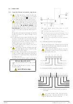
shown in Fig. 11.
Fig. 11.
Mounting the set in a 19” rack cabinet.
5.1.5.4. Preliminary considerations before connection.
•
In the description of this manual, reference is made to the
connection of terminals and switch operations that are
only available in some versions or devices with extended
backup. Ignore the related operations if your unit does not
feature them.
•
Thermal control of these devices is carried out with the
passage of forced air from the front to the rear.
The front surface and about 15cm on the rear side should
be left free of obstructions to facilitate the free circulation
of air for ventilation.
•
Follow and respect the instructions described in this sec-
tion referring to the installation of a single device or a
system in parallel.
•
Protection or external manual bypass board:
The system will have at least one short-circuit protec-
tion on the UPS’s power supply line.
It is advisable to have an external manual bypass board
fitted with input, output and manual bypass protections
in single systems.
For parallel systems,
it is essential
to have a distri-
bution or manual bypass board. The board’s circuit
breakers must be able to isolate a UPS from the system
in the event of a fault and power the loads with the
others, either during periods of preventative mainte-
nance or during breakdown and repair.
•
Upon request, we can supply an external manual bypass
board for a single device or parallel system.
You can also choose to manufacture it, taking into account
the version and configuration of the device or system avail-
able and the documentation contained in the CD-ROM or
pen drive relating to ‘Recommended installation’.
•
In the documentation supplied with this user manual
and/or on the CD-ROM or pen drive, information is
available on ‘Recommended installation’ for each input and
output configuration. This documentation includes wiring
diagrams and information about the sizes of the protections
and the minimum cross sections of cables connected to the
device according to their rated working voltage. All values
Fig. 9.
Vertically mounted tower-type model.
5.1.5.3. Mounting a rack in a 19” cabinet.
•
To mount a device in a 19” rack cabinet, proceed as follows
(see Fig. 10 and Fig. 11):
Using the supplied screws, fix the two adapter angles
for use as handles on each side of the UPS, respecting
your hand.
To install the device in a rack cabinet, it is necessary
to have internal lateral guides for use as supports. Al-
ternatively, and upon request, we can supply universal
slides for use as guides, for installation by the user.
Mount the guides at the required height, ensuring
correct tightening of the fixing screws and appropriate
fitting in the machining, according to each case.
Place the device onto the guides and insert it all the
way to the back.
Depending on the device model and weight, and/or
whether it is installed in the upper or lower part of the
cabinet, it is recommended that two people carry out
the installation operations.
Fix the UPS to the frame of the cabinet using screws.
Fig. 10.
Mounting a UPS in a 19” cabinet.
SLC TWIN RT2 T
UNINTERRUPTIBLE POWER SUPPLIES (UPS)
USER MANUAL


