


22
•
In parallel systems, the length and cross section of the
cables that go from the switchgear panel till one of the
UPSs and vice versa, will be the same for all of them without
any exception.
In the worst case, the following deviations have to be strictly
respected:
When the distance among the UPSs and the protection
panel is lower than 20 metres, the difference in the length
between the input and output cables of the equipments
has to be lower than 20%.
When the distance among the UPSs and the protec-
tion panel is higher than 20 metres, the difference in the
length between the input and output cables of the equip-
ments has to be lower than 10%.
4.3.8. Communication ports.
4.3.8.1. RS232 and USB interfaces.
•
Communication line (COM) is a very low voltage circuit
of safety. To preserve the quality, it has to be installed
separate from other lines that have dangerous voltages (energy
distribution line).
•
RS232 and USB interfaces are used by the monitoring soft-
ware and firmware updating.
•
It is not possible to use both ports at the same time.
•
Signal pin-out of the DB9 connector are shown in table 4.
RS232 port consists in a serial data transmission, so an im-
portant quantity of information can be sent through a com-
munication cable of three wires.
•
Physical structure of RS-232:
Pin #
Description
Input / Output
2
TXD (serial data transmission)
Output
3
RXD (serial data reception)
Input
5
GND (groundof the signal)
Input
Table 4.
Pin-out of the RS232 in the DB9 connector.
•
USB communication port is compatible with the USB 1.1 pro-
tocol for communication software.
4.3.8.2. Smart slot.
•
UPS's have a unique slot for TWIN PRO and two slots for
TWIN/3 PRO, hidden rear the covers stated in the views of
the equipment. One of them allows inserting the SNMP card
option, for controlling it via Web, and the second, which is
also optional, allows the remote management of the UPS
through Internet or Intranet.
•
For more information, contact with our
S.T.S.
or our nearest
distributor.
4.3.8.3. Relays interface (option).
•
Communication line (COM) is a very low voltage circuit
of safety. To preserve the quality, it has to be installed
separate from other lines that have dangerous voltages (energy
distribution line).
•
UPS has a dry contact card for the relays interface, it pro-
vides digital signals in a free potential way, with a maximum
applicable voltage and current of 240 V ac or 30 V dc and 1A.
•
This communication port makes possible the dialogue be-
tween the equipment and other machines or devices, through
the 5 dry contacts supplied in the terminal strip included in
the same card and to each one of them an alarm of the 8
available can be assigned (see table 5).
Also there are other three additional terminals with only one
common, for an installation of an external On/Off switch to
the equipment and a third one with free setting among EPO,
Shutdown or "On-Off" remote control.
From factory all contacts are normally opened, being able
to set them separately one by one, by means of the Hyper
Terminal software or equivalent.
•
The most common use of this type of ports is to provide the
needed information for the closing file software.
•
This card has a RS232 port through a RJ connector. So, in
case of requiring a DB9 connector, use the adaptor RJ / DB9
supplied with the relays interface card.
•
For more information, contact with our
S.T.S.
or our nearest
distributor.
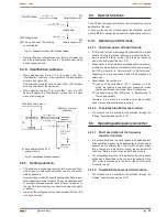
SW2 "On"
SW3 "Off"
SW1 (*)
Relays interface card
Internal
relays
14
7
1 (GND)
13 12 11 10
9
6 5 4 3 2
8
Fig. 14.
Relays interface pin-out.
Description
Nr pin
Input/output
Mains fault
Programmable
Output
Low battery
Programmable
Output
General alarm
Programmable
Output
Bypass status
Programmable
Output
Summary alarm
Programmable
Output
Battery test
Programmable
Output
Shutdown in process
Programmable
Output
Overload alarm
Programmable
Output
UPS signal "On"
1 (GND) - 14
Input
UPS signal "Off"
1 (GND) - 7
Input
Programmable signal as:
- EPO
- Shutdown on battery mode
- Shutdown on any mode
- Remote control "On-Off"
1 (GND) - 8
Input
Table 5.
Relays interface alarms.
Installation.
•
Remove the protection cover from the relays interface slot of
the equipment.
•
Take the relays interface card and insert it into the reserved
slot. Make sure that it is well connected, so the resistance
that the own connector inside the slot makes has to be over-
come.
USER MANUAL
Summary of Contents for SLC TWIN PRO Series
Page 2: ......
Page 43: ...43 SALICRU...


