Salicru SLC TWIN PRO Series User Manual Download Page 13

13

SALICRU

3.3.  Operating principle.

This manual describes the installation and operating of the Un-
interruptible Power Supply (UPS) from 

SLC TWIN PRO

 series 

as equipments that can operate separately or connected in 
parallel, without needing a centralised bypass. UPSs from 

SLC 

TWIN PRO

 series assure an optimal protection of any critical 

load, keeping the power supply voltage to the loads between the 
stated parameters, with no break, during a blackout, deterioration 
or perturbations of electrical commercial mains and with a wide 
range of available models (from 4 to 20kVA), it allows adapting 
the model to the end-user needs.
Thanks to the used technology, PWM (pulse width modulation) 
and double conversion, UPS from 

SLC TWIN PRO

 series are 

compact, cold, silent and high efficiency.
The double conversion principle cancels any perturbations from 
mains energy. A rectifier converts the AC alternating current from 
input mains into DC direct current, keeping an optimal battery 
charging level and supplying the inverter, and at the same time 
creates an AC sinewave voltage ready to feed the loads perma-
nently. In case of UPS input mains fault, the batteries supplies 
clean energy to the inverter.
The UPS design and construction from 

SLC TWIN PRO

 series 

has been done in accordance with the international regulations.
These equipments allow the upgrading by means of the connec-
tion of additional modules of the same power rate, to get redun-
dancy (i.e.: N+1) or to increase the capacity of the system.
So, this series has been designed to maximize the availability of 
the critical loads and to assure that your business is protected 
against perturbations of voltage, frequency, electrical noises, 
blackouts and mains faults, which are present in the energy 
distribution lines. This is the main target of the UPSs from 

SLC 

TWIN PRO

 series.

This manual can be applied to the standardised and stated 
models in table 1.

3.3.1.  Main features.

• 

True on-line double conversion and independent output fre-

quency from mains.

• 

Output power factor of 0,9 and pure sinewave, suitable for 

almost any kind of loads.

• 

Input power factor > 0,99 and high general efficiency (> 0,92 

for single phase input or > 0,93 for three phase). High en-

ergy saving and low cost for the user's installation (wiring) 

is achieved, as well as low input current distortion, so mains 

pollution is decreased.

• 

Great adaptability to the worst conditions of the input mains. 

Wide margins of the input voltage, frequency range and 

wave shape, so it is avoided the excessive dependence on 

the limited energy of the battery.

• 

Availability of battery chargers up to 12A in order to decrease 

the battery recharging time.

• 

Parallel redundant connection N+X to increase the reliability 

and flexibility. 4 equipments in parallel as maximum.

• 

High efficiency mode can be selected > 0,97 (ECO-MODE). 

Energy saving, which reverts to the user in an economy way.

• 

It is possible to start up the equipment without mains or the bat-

tery discharged. Watch this last aspect, because the back up 

time will be decreased as much discharged the batteries are.

• 

The technology of the smart management of the battery is 

very useful for making longer the accumulator lifetime and to 

optimise the recharging time.

• 

Standard communications options by means of RS-232 or 

USB ports.

• 

Control of the remote emergency power off (EPO).

• 

Control signal of the remote emergency power off (EPO).

• 

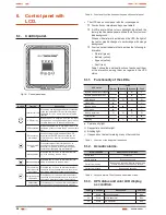
Interface between the user and the equipment through the 

control panel and LCD with led indicators, user friendly.

• 

Option cards are available to improve the communication ca-

pacity of connectivity.

• 

Easy firmware updating, no need to call to the Service and 

Technical Support (

S.T.S.

).

• 

Simplified maintenance, which allows replacing the batteries 

in a safety way without shutdown the UPS.

Model

Type

Input / output tipology

SLC-4000-TWIN PRO

S

ta

nda

rd

Single phase / Single phase

SLC-5000-TWIN PRO
SLC-6000-TWIN PRO
SLC-8000-TWIN PRO
SLC-10000-TWIN PRO
SLC-8000-TWIN/3 PRO

Three phase / Single phase

SLC-10000-TWIN/3 PRO
SLC-12000-TWIN/3 PRO
SLC-15000-TWIN/3 PRO
SLC-20000-TWIN/3 PRO
SLC-4000-TWIN PRO(B0)

N

o ba

tte

rie

s

Single phase / Single phase

SLC-5000-TWIN PRO(B0)
SLC-6000-TWIN PRO(B0)
SLC-8000-TWIN PRO(B0)
SLC-10000-TWIN PRO(B0)
SLC-8000-TWIN/3 PRO (B0)

Three phase / Single phase

SLC-10000-TWIN/3 PRO (B0)
SLC-12000-TWIN/3 PRO (B0)
SLC-15000-TWIN/3 PRO (B0)
SLC-20000-TWIN/3 PRO (B0)
SLC-4000-TWIN PRO(B1)

E

xt

en

de

r b

ac

k u

p t

im

e

Single phase / Single phase 

SLC-5000-TWIN PRO(B1)
SLC-6000-TWIN PRO(B1)
SLC-8000-TWIN PRO(B1)
SLC-10000-TWIN PRO(B1)
SLC-8000-TWIN/3 PRO (B1)

Three phase / Single phase 

SLC-10000-TWIN/3 PRO (B1)
SLC-12000-TWIN/3 PRO (B1)
SLC-15000-TWIN/3 PRO (B1)
SLC-20000-TWIN/3 PRO (B1)

Table 1. 

Standard models.

Summary of Contents for SLC TWIN PRO Series

Page 1: ...PS LIGHTING FLOW DIMMER STABILIZERS ILUEST SWITCH MODE POWER SUPPLY STATIC INVERTERS PHOTOVOLTAIC INVERTERS VOLTAGE STABILIZERS AND POWER LINE CONDITIONERS UPSSLCTWINPROseries 4 to 20 kVA UNINTERRUPTI...

Page 2: ......

Page 3: ...ing 5 1 Commissioning 5 1 1 Controls before commissioning 5 2 Start up and shutdown of the UPS 5 2 1 Start up of the UPS with mains present 5 2 2 Start up of the UPS without mains 5 2 3 UPS shutdown w...

Page 4: ...structions for safety of the things To not respect such instructions can damage the goods Precaution symbol Read the paragraph text and take the stated preventive mediums it contents the basic instru...

Page 5: ...chnical Regulations or standards of the country Use approved cables only Protection Earth cable of the UPS drives the leakage current of the load devices An isolated earth cable has to be installed as...

Page 6: ...r cause can make an electrical discharge of high voltage and it is restricted to qualified staff only Do not open the equipment A part from the implicit stated risks any action that make the modificat...

Page 7: ...hem Do not modify its length In those equipments requested without batteries their ac quisition installation and connection of themselves will be done by the end user and under his responsibility Data...

Page 8: ...ive EMC In accordance with the specifications of the harmonized stand ards Standards as reference EN IEC 62040 1 Uninterruptible power supply UPS Part 1 1 General and safety requirements for UPS s use...

Page 9: ...due to the constant evolution of the product some discrepancies or small contradictions can arise In front of any doubt the labelling of the equipment will always prevail i Figures regarding its main...

Page 10: ...USB Protection cover for external batteries IEC output connectors Protection cover for manual bypass switch maintenance and output Protection cover for power blocks USB RS 232 EPO Protection cover for...

Page 11: ...11 SALICRU Battery switch Protection cover for power blocks Batteries module for models 10 kVA Batteries module for models up to 10 kVA Battery switch Power blocks Fig 3 Rear view batteries module...

Page 12: ...ews and electrical cables Batteries owned by the client will be installed out from the case or cabinet of the UPS Under request it is possible to supply the acces sories screws and electrical cables n...

Page 13: ...user s installation wiring is achieved as well as low input current distortion so mains pollution is decreased Great adaptability to the worst conditions of the input mains Wide margins of the input v...

Page 14: ...tor The big IT systems based on LANs and WANs that integrate servers with different platforms they have to include an easy way of controlling and management at the manager system dis posal This facili...

Page 15: ...es type B for RCD devices and C characteristic for circuit breakers For the output load feeding C characteristic for circuit breaker Regarding the size they will be as minimum to the cur rents stated...

Page 16: ...any start it up according to the instructions described in this manual and charge them for 2 hours from floating level In parallel systems it is not needed to make the connection among the equipments...

Page 17: ...all ends of the cables connected to the power blocks input output and by pass Check the correct torque in the screws of the power blocks In installations with only one UPS the Jumper cable as bridge...

Page 18: ...is done through the terminals of the own UPS MC coil out and MC coil in R N R S T N R N U N 1 3 2 SAI Backfeed protection connection in TWIN 3 PRO 10 kVA Backfeed protection signal Backfeed protectio...

Page 19: ...wn in any of the machines connected to the device causing a short circuit it will affect to no more than the line that is faulty The rest of the connected loads will have their continuity as sured due...

Page 20: ...of each equipment with its external battery cabinet s has to be done like if they were single units completely separate from the rest ones Each battery module is independent for each equip ment It is...

Page 21: ...tput static bypass this last one for TWIN 3 PRO 10 kVA models only also a manual bypass with mechanical lock see figures 12 and 13 This switchgear panel allows isolating only one equipment from the sy...

Page 22: ...oltage circuit of safety To preserve the quality it has to be installed separate from other lines that have dangerous voltages energy distribution line UPS has a dry contact card for the relays interf...

Page 23: ...imum before using the UPS for first time For models with single phase input TWIN PRO or three phase TWIN 3 PRO up to 10 kVA It will be necessary to supply power supply voltage to the equipment and tur...

Page 24: ...attery switch is in position On models B0 and B1 Turn the input M1 and bypass M2 circuit breakers to On Switch M2 is only available in models TWIN 3 PRO 10 kVA In equipments with single phase input TW...

Page 25: ...will transfer to Bypass mode Put all the equipments on manual bypass To do it re move the cover from manual bypass switch which is located at the back of each equipment and turn all the switches to p...

Page 26: ...he UPSs have to be set contact with the S T S Press over the shutdown key in any UPS for more than 3 seconds and each one will be shutdown supplying output voltage through the bypass Turn On the outpu...

Page 27: ...ot be fed Turn the manual bypass switch of the panel to Off UPS and put the mechanical lock To avoid wrong manoeuvring the mechanical lock has to be fit otherwise the equipment and loads are exposed t...

Page 28: ...g Press the key for 1 sec as minimum to validate the modified option and change the settings Table 6 Functionality of the buttons or keypad of the control panel The UPS has a control panel with the fo...

Page 29: ...TWIN Blue 72 Warning On maintain Bypass UPS only 8 20 kVA TWIN 3 Blue Code Condition Description Color LCD 81 Fault Heatsink over temperature Red 82 Alarm Ambient over temperature UPS only 4 10 kVA TW...

Page 30: ...ad level connected to the UPS UPS power supply information three phase input UPS output information Equipment Battery information Fig 18 Main screen of the equipment with three phase input All the scr...

Page 31: ...supply fails due to fault or wrong the equipment will transfer to Battery mode to feed the load s properly Fig 24 Frequency converter mode screen This function can be activated through the settings of...

Page 32: ...ucture of the main menu includes six submenus UPS status Event log Measurement Control Identification Setting With password only and by the S T S 6 3 2 UPS status submenu When pressing the key for les...

Page 33: ...ucture of UPS status menu Structure of main menu Press 1 sec Fig 31 UPS status screen Press 1 sec Press o 1 sec Structure of Data logger submenu Structure of main menu Press 1 sec Fig 32 Event logger...

Page 34: ...rd only Fig 34 Control submenu screens 6 3 5 Control submenu When pressing the key the key for less than 1 sec from this Control submenu it is accessed to the control structure see figure 34 Shutdown...

Page 35: ...ndard configuration from factory 6 4 1 Operating on ECO mode 6 4 1 1 Short description of the ECO mode ECO mode function allows supplying the load s from mains directly through the internal filters on...

Page 36: ...en used for long time In hot areas battery has to be charged every 2 months The charging time has to be 12 hours as minimum Under normal conditions the battery lifetime is from 3 to 5 years 25 C In ca...

Page 37: ...the UPS cooling and the ambient temperature of the room NTC abnormal UPS internal fault Consult with the S T S Communication cable male disconnected Para cable Male Loss Alarm code E3 Parallel bus ca...

Page 38: ...oltage Inv Under Voltage Alarm code 33 UPS internal fault Consult with the S T S Inverter Softstart Failed Inv Softstart Fail Alarm code E34 UPS internal fault Consult with the S T S Negative Power Fa...

Page 39: ...7 3 1 Covered product UPS SLC TWIN PRO series 7 3 2 Warranty terms This product is guaranteed against any parts and or labour defect for 12 months period from its commissioning by our company staff o...

Page 40: ...age THD with non linear load 5 Output voltage recovering time 100 ms IEC 62040 3 70 ms IEC 62040 3 60 ms IEC 62040 3 Transient response of the output voltage with load fluctuation of 0 100 0 9 7 7 Tra...

Page 41: ...elation to the working height 8 2 Glossary AC It is nominated as alternating current abbreviation in Spanish CA and in English AC to the electrical current in which the magnitude and direction varies...

Page 42: ...rcuit when it over comes the maximum set values On Line mode Regarding to an equipment it is on line when it is connected to the system and it is in operation and usually has its power supply turned o...

Page 43: ...43 SALICRU...

Page 44: ...NCIA VALLADOLID ZARAGOZA BRANCHES AND SERVICES AND TECHNICAL SUPPORT S T S CHINA FRANCIA HUNGR A MARRUECOS M XICO PORTUGAL REINO UNIDO SINGAPUR SUBSIDIARIES ALEMANIA ARABIA SAUD ARGELIA ARGENTINA B LG...

Reviews: