


Page 14
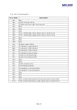
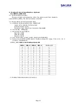
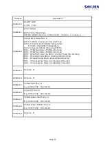
Address
Description
Address 0
On/Off R/W
0=Off 1=On
Address 1
Error Code R
Bit7-0: Error Fault Code
Bit15-8: Which one error 0: Main Unit 1: module 1 2: module 2 .....
Address 2
Status Bit & Output Bit R
Bit15: 0.Water Cool Type 1.Fan Cool Type
Bit14: 0.Control Outlet Water Temperature
1.Control Inlet Water Temperature
Bit13: 0.Run Cool Mode 1.Run Heat Mode
Bit6: 0.FAN No2 Stop 1.FAN No2 Running
Bit5: 0.FAN No1 Stop 1.FAN No1 Running
Bit4: 0.Cooling Tower Fan Stop 1.Cooling Tower Fan Running
Bit3: 0.Cooling Pump Stop 1.Cooling Pump Running
Bit2: 0.Freeze Pump Stop 1.Freeze Pump Running
Bit1: 0.Compressor2 Stop 1.Compressor2 Running
Bit0: 0.Compressor1 Stop 1.Compressor1 Running
Address 3 Reserve R
Address 4 Reserve R
Address 5
Chilled Set Temp R
E.g. 235=23.5C 190=19.0C
Address 6
Ambient Temp R
E.g. 235=23.5C 190=19.0C
Address 7
Chilled Water Inlet Temp R
E.g. 235=23.5C 190=19.0C
Address 8
Chilled Water Outlet Temp R
E.g. 235=23.5C 190=19.0C
Address 9 Reserve R
Summary of Contents for FCA 201
Page 1: ...Ref S FR 266 11 19 Models FCA 201 601 AIR COOLED MODULAR CHILLER ...
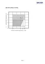
Page 6: ...Page 5 Operating Range Cooling ...
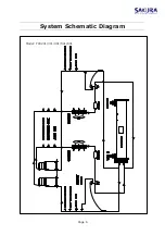
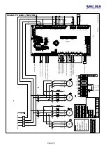
Page 7: ...System Schematic Diagram Page 6 Model FCA201 301 401 501 601 ...
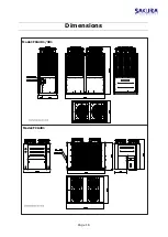
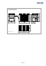
Page 17: ...Dimensions Page 16 Model FCA201 301 Model FCA401 ...
Page 18: ...Page 17 Model FCA501 601 ...
Page 25: ...Page 24 FCA201 301 401 501 601 Maintenance Maintenance ...


