


HS2/AS2 Series
41
42
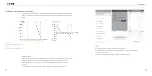
Connecting Procedures:
1. Loosen the lock screws on positive and negative connector.
2. Strip the insulation of the positive and negative cables with 8-10mm length.
positive cable
negative cable
Figure 5.6
Striping off the insulation skin of cables
3. Assembly the positive and negative cables with corresponding crimping pliers.
Figure 5.7
Inserting cables to lock screws
4. Insert the positive and negative cable into positive and negative connector. Gently pull the cables backward
to ensure firm connection.
Figure 5.8
Inserting crimped cables to connectors
5.Fasten the lock screws on positive and negative connectors.
Figure 5.9
Securing the connectors
6.Make sure the DC switch is at OFF position
Figure 5.10
DC switch
7.Connect the positive and negative connectors into positive and negative DC input terminals of the inverter,
a
“
click
”
should be heard or felt when the contact cable assembly is seated correctly.
Figure 5.11
Plug in PV connectors
Pv Array
PV+
PV-
PV+
-
+
PV-
-
+