background image

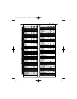
P

ARTS

L

IST

PART

KK

Y

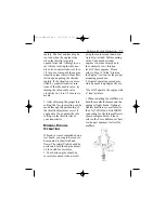
HH

170R01

FA-325R5D

FA-450R3D

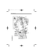
01 Cylinder, Left

170R01

300ttDP01A

150SDP01

02 Cylinder, Right

06 Piston

5606A

6506

150S06

07 Piston Pin

6507

6507

12007

08 Piston Pin Retainer (6 Pc)

6508

6508

300T08

09 Piston Ring

6509

6509

300T09A

10 Connecting Rod

170R10

325R510

450R3D10

11 Linked Connecting Rod

170R11

325R511

450R3D11

12 Connecting Rod Link Pin & Screw

170R12

325R512

13 Connecting Rod Screw

14 Cylinder Screw Set

5014

6514

6514

15 Crankcase

170R15

325R515A

450R3D15

16 Front Shield

325R516

17 Rear Cover (A)

170R17

325R517

450R3D17

18 Rear Cover (B)

170R18

325R518

450R3D18

19 Breather Nipple

6519

4019

4019

20 Front Ball Bearing

120/20A

270T20A

450R3020

21 Main Ball Bearing

300T21

22 Rear Ball Bearing

270T22

450R3D22

23 Crankshaft

170R23

325R523

450R3D23

24 Pinion-Crankshaft

25 Pinion Gear Pin

26 Collar, Crankshaft

325R526

27 Tapered Collet & Drive Flange

120/27

270T27B

450R3D27

28 Prop Washer & Nut

170R28A 12028A

450R3D28

29 Prop Nut, Spinner

12029

30 Prop Nut, Electric Starter

31 Crankcase Screw Set

170R31

325R531

450R3D31

32 Engine Gasket Set

170R32

325R532

450R3D32

33 Cam Gear Housing

170R33

300T33

34 Cam Gear, Left

325R34

35 Cam Gear, Right

6535A

120S35

36 Cam Gear Shaft

170R36

325R536

4036

37 Teflon/Steel Washer Set

170R39

325R537

120S37

38 Tappet (2 Pc)

5038

5038

120S38

39 Pushrod (2 Pc)

170R39

325R539

450R3039

40 Pushrod Cover Rubber Seal (Pr)

5040

325R540

450R3D40

41 Rocker Arm (Pr)

5041

4041

12041

42 Rocker Arm Screw Nut (2 Sets)

5042

4042

12042

43 Rocker Arm Pin (2 Pc)

5043

4043

12043

44 Rocker Arm Bracket, Left

150S44

45 Rocker Arm Bracket, Right

150S45

46 Valve-In/Out (Pr)

5646

325R546

120S46

47 Valve Spring, Keeper, Retainer (2 sets)

5047

6547

120S47

48 Valve Retainer (4 Pc)

5048

5048

120S48

49 Rocker Arm Cover (Pr)

50GK49

50GK49

120S49

50 Cam Gear Base (A)

325R550A

51 Cam Gear Case (B)

325R551

52 Counter Gear

325R552

53 Counter Gear Shaft

325R553

54 Cam Gear Base Strut

325R554A

55 Impeller Fan

325R5555

56 Crank—Impeller

325R556

57 Ball Bearing, Impeller Axle

325R557

58 E-Clip, Impeller Ball Bearing

325R558

64 Air Pump Assembly

65 Air Pump Housing

66 Diaphragm & Check Valve Rubber Set —

17

PART

KK

Y

HH

170R01

FA-325R5D

FA-450R3D

67 Diaphragm, Pushrod, Return Spring

68 Check Valve-In/Out (Pr)

69 Intake Manifold, Left

170R69

325R569

450R3D69

70 Intake Manifold, Right

71Intake Manifold Nut

325R571

450R3D71

72 Intake Manifold w/Primer

325R572

73 Muffler, Left

170R73

130T73

450R3D73

74 Muffler, Right

170R74

130T74

450R3D74

78 Muffler Ring

325R578A

79 Muffler Gasket (5 Pc)

170R79

325R579

450R3D79

80 Muffler Nut (2 Pc)

170R80

325R580

450R3D80

81 Priming Harness

325R581

82 Carburetor-Complete

170R82

821 Carburetor-Complete, Left

325R821A

4503D821

822 Carburetor-Complete, Right

831 Carburetor Body Assembly, Left

325R5831

120S831

832 Carburetor Body Assembly, Right

83 Carb Body Assembly

170R83

84 Spray Bar Assembly

85 High Speed Needle Valve

170R85

5085

12085

86 High Speed Needle Valve Extension

5086

4086

450R3D86

87 Throttle Barrel Assembly

170R389

325R587A

120S87A

88 Throttle Lever

5088

325R588

5088A

89 Idle Needle Valve

170R389

5089

120S89

90 Carburetor Screw & Spring Set

170R390

325R590

120S90A

91 Carburetor Gasket Set

170R391

325R591

450R3D91

92 Choke Valve Assembly

120S92

93 Intake Velocity Stack

94 Glow Plug Harness

170R94

325R594

450R3D94

95 Engine Mount

170R95

325R595A

300T95B

96 Tool Set

170R96

325R596

270T96B

97 Instruction Manual

170R97

325R5D97

99 Muffler Bracket

101 Twin Carburetor Control Assembly

102 Fuel Pump System

103 Carburetor Fitting Flange w/Screw

450R3D103

104 Cam Gear Bearing, Rear

105 Cam Gear Bearing, Front

106 Cam Gear Bearing Shield

107 Carburetor Bracket

109 F-1 Fuel Filler

40109

110 Anti-Loosening Prop Nut

170R110

270T110

116 M3 Nut for Spinner

117 M4 Nut for Spinner

118 M5 Nut for Spinner

119 Rear Cover w/Integrated Motor Mount —

121 Crank Pin Spacer, Teflon

170R121

325R5121

450R3D121

125 Muffler, Number 1 Cylinder

325R5125

126 Muffler, Number 2 Cylinder

325R5126

127 Muffler, Number 3 Cylinder

325R5127

128 Muffler, Number 4 Cylinder

325R5128

450R3D128

129 Muffler, Number 5 Cylinder

325R5129

450R3D129

130 Muffler, Adapter Nut

170R130

450R3D130

MAN Saito Twin Cylinder Manual

131 Throttle Valve Extension Adapter

170R131

781 Flex Muffler #1, #3 cyl.

170R701

782 Flex Muffler #2 cyl.

170R782

786 Carburator Tie

170R786

M

UL

TI

-C

YLINDER

C

R

OSS

R

EFERENCE

C

HAR

T

Saito manual doc  11/12/01  2:11 PM  Page 17

Summary of Contents for FA-170R3-D

Page 1: ...INSTRUCTION MANUAL FA 170R3 D FA 325R5 D FA 450R3 D Multi Cylinder Four Stroke Engines Saito manual doc 11 12 01 2 10 PM Page a1...

Page 2: ...VERY IMPORTANT Failure to read and follow these instruc tions before you proceed may result in engine damage and the voiding of your warranty Saito manual doc 11 12 01 2 10 PM Page a2...

Page 3: ...all spectators especially children are at least 20 feet away 2 Use the correct size and pitch of propeller for your engine refer to the propeller chart in this man ual 3 It is extremely important to b...

Page 4: ...ll loose objects screwdrivers pencils nickel cad mium starters etc should be removed from your pockets so they do not fall into the propeller 4 Glow plug clips and cords are kept away from the propell...

Page 5: ...Saito engine SUPPORT EQUIPMENT The following items which are not included with your Saito engine are necessary in order to operate the model engine Fuel For maximum protec tion and longevity of Saito...

Page 6: ...micro switch to the positive terminal on the Ni Cad battery c Attach the single lead from the ground wire to the negative terminal on the Ni Cad battery Please refer to Fig 1 d The on board battery sy...

Page 7: ...board glow system is highly recom mended This will guarantee a smooth reliable idle If an on board glow system will NOT be utilized replacement of the standard McCoy glow plugs with a hotter plug such...

Page 8: ...e and down the pushrod tubes 40 will ensure proper lubrication for the first run Regardless of the mounting met hod chosen for break in the following procedures areapplicable 1 Use a break in fuel as...

Page 9: ...hers and that the lines are properly connected 5 Fill the fuel tank 6 Check to make sure the glow plugs are not connected to the heat source glow plug clip lock ing socket Note If an electric starter...

Page 10: ...stall the plug START THE ENGINE 11 Close the throttle to 1 4 to 1 3 open position 12 Rotate the propeller clockwise until it s against the compression stroke 13 Rotate the propeller in a coun terclock...

Page 11: ...ngine becomes hydro locked simply remove the glow plugs and turn the engine over a few times with the chicken stick or electric starter The excess fuel will be forced to exit the engine via the cylind...

Page 12: ...ely 200 300 rpm by turning the high speed needle valve counterclockwise LOW SPEED CARBURETOR ADJUSTMENTS The low speed or idle needle valve 89 is pre adjusted at the factory for best performance dur i...

Page 13: ...r engineis ready to be mounted to theaircraft and flown The initial flight should be performed with the engine adjust ed for a rich fuel mixture 1 Your Saito engine should be securely mounted to the a...

Page 14: ...ding the warranty however disassembly of the cylinders crankshaft and cam gear assembly should be done only by the Saito Service Center because of the special jigs and tools required If you have any q...

Page 15: ...eter for precise engine adjustments 5 Use an after run oil when you re finished flying for the day 6 For long term storage make sure there is no fuel left in the tank and the engine Remove the glow pl...

Page 16: ...l times to clear cylinder s Disconnect battery and rotate propeller several times to clear cylin der s Close high speed needle 1 2 turn and start again Repeat engine is run ning smoothly Open high spe...

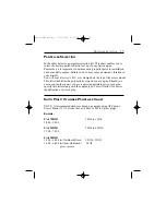
Page 17: ...is letter identifies the production version of your engine Should you ever need to order a part or have a question pertaining to your engine specify this letter along with the engine type This will al...

Page 18: ...170R3D and FA450R3D have muffler inserts that allow the use of short pipes standard issue that are 14mm For use of flexible mufflers remove the adapter nut installed in the cylinder SPECIFICATIONS Ite...

Page 19: ...Housing 66Diaphragm CheckValveRubberSet 17 PART KK Y HH 170R01 FA 325R5D FA 450R3D 67Diaphragm Pushrod ReturnSpring 68CheckValve In Out Pr 69IntakeManifold Left 170R69 325R569 450R3D69 70IntakeManifol...

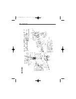
Page 20: ...18 PARTS LIST FA170R3 Saito manual doc 11 12 01 2 11 PM Page 18...

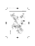
Page 21: ...19 PARTS LIST FA 325R5 D Saito manual doc 11 12 01 2 11 PM Page 19...

Page 22: ...20 PARTS LIST FA 450R3 D 13 Saito manual doc 11 12 01 2 11 PM Page 20...

Page 23: ...to engines are guaranteed against workmanship and manufacturing defects for a period of 3 years from the original date of purchase This warranty is limited to the original pur chaser of the engine and...

Page 24: ...air cost exceed 50 of the retail purchase cost you will be provided with an esti mate advising you of your options Any return freight for non warranty repairs will be billed to the consumer 5 Please a...

Page 25: ...________________ Owner s Name __________________________________________________ Street Address ____________________________________________________ City State Zip ____________________________________...

Page 26: ...Exclusively Distributed by Horizon Hobby Distributors Inc Champaign IL 61822 Copyright 1998 Stock SAIMAN1 Saito manual doc 11 12 01 2 11 PM Page 24...

Page 27: ...25 Saito manual doc 11 12 01 2 11 PM Page 25...

Reviews: