background image

5

Installation

IRIDIUM

2.3

Cable Overview

Cable 1
Scanbus
Cable:

9*0.22 mm

2

shielded
shield connected to ground

Cable connector type:

9 pole sub-d male

Transceiver

Description

Handset

Colour

1

NC

1

2

data+

2

white

Twisted

3

data-

3

brown

pairs

4

AF+

4

green

Twisted

5

AF-

5

yellow

pairs

6

GND

6

grey

Twisted

7

+24V DC

7

pink

pairs

8

RX_AF+

8

blue Twisted

9

RX_AF-

9

red

pairs

shield

GND

shield

2

3

4

5

6

7

8

9

1

10

36088

0514

Cable 2
Phone
Cable connector type: RJ 11

Transceiver

Description

1

NC

2

3

phone1-

4

NC

Cable 3
Data
Cable:

9*0.22 mm

2

shielded
shield connected to ground

Cable connector type:

9 pole sub-d male

Transceiver

Description

1

DCD

2

received data

3

transmitted data

4

data terminal ready

5

serial  GND

6

data set ready

7

request to send

8

clear  to  send

9

RI

shield

GND

Cable 4
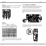
Power supply

Pin no.

Description

Colour

1

10-32V DC

red

2

0V  DC

black

3

NC

white

4

GND

green

Front view

4

3

1

2

36662A

Summary of Contents for SC4000 Iridium

Page 1: ...TECHNICAL MANUAL SAILOR SC4000 IRIDIUM ...

Page 2: ...tion Your Iridium equipment is a modular system that consists of a transceiver unit control handset unit antenna unit and an optional analogue PSTN telephone PABX You can make and receive voice calls on the control handset and the analogue PSTN telephone You can connect up to four handsets and one analogue PSTN telephone or PBX switchboard to the system The system provides intercom for internal ca...

Page 3: ...to Place the Satellite Transceiver Box 7 2 5 How to Mount the Satellite Transceiver Box 7 2 6 How to Put on the Finishing Cover 8 2 7 How to Insert the SIM Card 9 2 8 Optional SIM card Reader 9 2 9 How to Remove the Finishing Cover 10 2 10 Installation of the Antenna 11 2 11 Analogue telephone 13 2 12 Data Interface 14 2 13 External Ringer Interface 14 2 14 Reset Button 14 Appendix A 17 Spare Part...

Page 4: ...mpedance 50 Ω Multiplexing Method TDMA FDMA Average Power during a transmit slot max 7W Average Power during a frame typical 0 6W Receiver Sensitivity at 50 Ohm typical 118 5 dBm Receiver Spurious Rejection at offsets 1 MHz typical 60 dB Voice Data Rate 2 4 kbit s QPSK Antenna Helical omni directional 210 3 dB beam width Fibreglass radome ø 96 mm Link Margin 16 dB Antenna Tracking Capability Turn ...

Page 5: ...tions Transceiver Operating temperature 10 C to 55 C Storage temperature 30 C to 70 C Antenna Temperature EME 35 C to 55 C Rel humidity Up to 95 at 40 C Icing survival only Up to 25 mm of ice Precipitation Up to 100 mm hour Wind velocity Up to 100 knots Vibration IME 2 50 Hz 1 g EME 4 33 Hz 1 g Weight Transceiver 2 7 kg Antenne 220 g Handset cradle 570 g 0514 ...

Page 6: ...nd Mk4 The version can easily be determined by looking at the area around the SIM card reader 2 2 Configuration of Single Channel Unit L1 35423E 10 32V DC PABX Phone DTE 2 3 4 1 Antenna Unit Max cable loss 3dB Iridium L1 L2 100 metres L2 Box Connection 5 1 Handset Control Handset Transceiver Unit Control 6 GPS Mk2 Mk3 Mk4 ...

Page 7: ...F 9 red pairs shield GND shield 2 3 4 5 6 7 8 9 1 10 36088 0514 Cable 2 Phone Cable connector type RJ 11 Transceiver Description 1 NC 2 phone1 3 phone1 4 NC Cable 3 Data Cable 9 0 22 mm2 shielded shield connected to ground Cable connector type 9 pole sub d male Transceiver Description 1 DCD 2 received data 3 transmitted data 4 data terminal ready 5 serial GND 6 data set ready 7 request to send 8 c...

Page 8: ... R182 R179 R147 R138 R192 R204 R190 C129 R140 C209 C210 V61 R35 R199 V68 L5 V55 R133 C185 V43 R137 V54 T2 V51 V50 R131 R139 R188 V32 C126 R194 R143 R207 C145 R200 V56 R196 V67 R214 C159 R211 R212 C73 R148 V33 R62 V26 V11 V27 C25 V12 R217 R15 R97 N15 C204 V60 R198 V57 R104 C125 C99 C49 R92 C181 R112 C186 C188 C161 R114 R91 R87 R115 C182 C190 R150 C191 R94 C173 C174 R86 C205 C48 R113 C189 C148 C53 R...

Page 9: ...needed If the system includes more than one control unit it is needed to remove some of the default terminations Belowtwoexamplesofscanbustermination is given when the system includes several control units 38635 Box Connection Transceiver Unit Control Unit Terminated Terminated Connection Box Control Unit Transceiver Unit 38636 Terminated Terminated ...

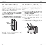
Page 10: ...ed in the package The screws are posi tioned as shown below 0514 First tighten three of the screws The wall surface should be plane If there is a discrepancy in planeness exceeding 1 mm level the discrepancy up by shims or washers under the fourth screw before this is tightened 2 6 How to Put on the Finishing Cover When the satellite transceiver box has been mounted on the wall put on the finishin...

Page 11: ...ing cover protecting the SIM card reader Then go through each of the follow ing steps Unlock the SIM card holder by pushing the lock with your finger nail c 0514 Lift the SIM card holder so that the slot points upwards d Insert the SIM card in the slot Make sure that the cut off corner of the card is placed as shown in the picture e Push the SIM card holder back down and lock it by pushing the loc...

Page 12: ...ermanentSIMcardisrequired Remove the lid by removing the 2 umbraco screws After inserting the card put the lid back on 2 9 How to Remove the Finishing Cover You may need to dismount the satellite transceiver box from the wall e g in connection with service For access to the mounting screws the finishing cover can be removed from the satellite transceiver box as follows c Put a screwdriver into the...

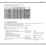
Page 13: ...6 0 mm 125 mm N MALE 79 001 SUCOFEED 7 8 77 520 50 m 27 8 mm 220 mm N MALE 79 003 FEMALE 79 004 2 10 Installation of the Antenna One of the advantages of this equipment is the easy to handle lightweight and rugged antenna Because the IRIDIUM system is characterised by a good link margin the antenna is a passive quadrifillar helix type requiring noexternalpowersupplyandconsistingofonlynonmoving par...

Page 14: ...the GPS originatedfromtheIridiumequipment Thiscanbeavoided by ensuring a distance of at least 1 m between the two antennas Inmarsat equipment TheoperatingfrequencybandsoftheiridiumandInmarsat systems are neighbours and it is not in any way by any technical solution possible to completely separate these bands This means that interference from Inmarsat can be expected especially if the antennas are ...

Page 15: ...ard analogue PSTN telephone directly to this interface for crew calling or as an office phone With a PABX you can add more telephone lines for multiple phones ie office network The interface handles the following tasks generates DC current to the phone PABX in both idle and active mode generates ringing voltage detects call requests from a phone PABX detects DTMF tones from a phone PABX outputs 12...

Page 16: ...act your Iridium Service Provider who can supply you with the Iridium Data Interface software Open 60V RMS Pin 2 3 90V RMS Pin 1 2 75V RMS 2 13 External Ringer Interface The external ringer output pin in the Service NMEA port can control an optional ringer or a lamp This is very useful in noisy environments or when there is a need for ringing indication at more locations The output is an open coll...

Page 17: ...15 Installation IRIDIUM 0514 ...

Page 18: ...16 Installation IRIDIUM 0514 ...

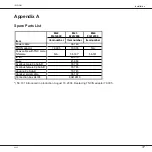
Page 19: ... 005 79 005 N A Coax cable with TNC male N female N A 56 181 56 181 ID kit 49 310 Fuse 45 669 Scanbus male 9p Sub D 78 758 Scanbus female 9p Sub D 78 765 Housing 9p Sub D 78 745 Handset spiral cable 56 102 Connection box H4196 80419610 56 181 introduced in production August 16 2004 Replacing TNC N adaptor 79 005 17 Installation IRIDIUM 0225 ...

Page 20: ...Thrane Thrane A S info thrane com www thrane com ...

Reviews: