25
SAILFISH
360 CC
| VSR BATTERY SYSTEM - “THE SMART BATTERY SWITCH”
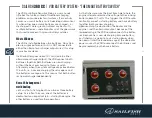
The VSR, or Voltage Sensitive Relay, is a very handy
little box that solves a load of traditional charging
problems on marine electrical systems. It essentially
serves as a smart battery switch deciding automatical-
ly when either one or more batteries are charged – or
discharged. It works great on almost any boat with
multiple batteries – and eliminates all of the guesswork
that used to come with manual battery switches.
What a VSR does
The VSR is installed between two batteries. Many Peo-
ple are surprised to learn that it is NOT connected to
either the alternator or charger output wires! Its setup
is much more clever.
It either battery goes above 13.7 volts (due to either
alternator or charger output), the VSR connects both
batteries together. Both batteries are now charging –
without the boat ever having to throw a switch.
Alternately, when the system voltage drops back below
12.6 volts, i.e., no more charging, the relay opens and
the batteries are separate. This means that both batter-
ies now discharge independently.
How a VSR changes real
world boating
Let’s say that a fishing boat has a two or three battery
setup. As is often the case, one of the batteries is
dedicated to an important job – starting the engine. The
other battery is used for other operations.
As the fisherman runs the boat from hole to hole, the
engine alternator elevates the voltage to the cranking
battery above 13.7 volts. This triggers the VSR to auto-
matically connect a starting battery and house battery
together. Both are now charging.
Upon reaching his destination, the boater kills the
engine – and the alternator output. Because of the
lowered voltage, the VSR now disconnects the batter-
ies. Because he is now discharging only one battery,
our fisherman is going to have starting power when
he needs it later.Once underway again, the alternator
power causes the VSR to reconnect the batteries and
begins replenishing the house battery.
Summary of Contents for 360 CC
Page 1: ...SAILFISH 360 CC OWNER S MANUAL...
Page 9: ...8 SAILFISH 360 CC BOAT SAFETY WARNING LABEL LOCATIONS InsideBatterySwitchDoors...
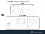
Page 12: ...11 SAILFISH 360 CC BATTERY SELECTOR PANEL AND WIRING BackViewWithWiring FrontView...
Page 15: ...14 SAILFISH 360 CC HEAD WASTE PLUMBING DIAGRAM DownloadHiResolutionDiagram...
Page 16: ...15 SAILFISH 360 CC RAW WATER PLUMBING DIAGRAM DownloadHiResolutionDiagram...
Page 17: ...16 SAILFISH 360 CC FRESHWATER PLUMBING DIAGRAM DownloadHiResolutionDiagram...
Page 18: ...17 SAILFISH 360 CC AIR CONDITIONER PLUMBING DIAGRAM DownloadHiResolutionDiagram...
Page 21: ...20 SAILFISH 360 CC UFLEX POWER STEERING SYSTEM MERCURY...
Page 44: ...43 SAILFISH 360 CC OPTIONAL REAR SHADE EXTENSION...
Page 46: ...45 SAILFISH 360 CC ELECTRONIC ACTUATED BOW TABLE...
Page 48: ...47 SAILFISH 360 CC ADJUSTABLE HELM SEAT DRIVING PLATFORM HelmSeatSlideSwitch...
Page 50: ...49 SAILFISH 360 CC DIVE DOOR BOARDING LADDER...
Page 56: ...55 SAILFISH 360 CC OFFSHORE INVERTER SYSTEM U S...
Page 57: ...56 SAILFISH 360 CC OFFSHORE INVERTER SYSTEM EUROPEAN...

