background image

Model F@st™2864 Router User’s Guide


Troubleshooting


19


Interpreting the LED Display 

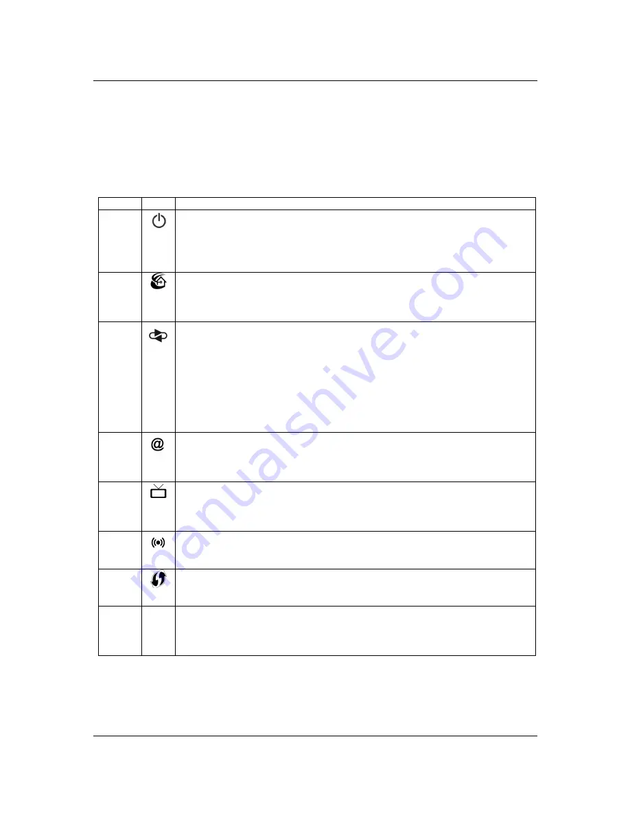
The LED indicators on the front and rear of the router give you a visual clue to the router’s activity. When 
the router is configured and working correctly and its power is cycled, the seven front panel LEDs each 
briefly turn on/off in a “walking” pattern sequencing from the bottom to the top and back to the bottom. 
The following table shows the possible states indicated by the LEDs. If the LEDs indicate a problem, refer 
to the “Resolving Specific Issues” section later in this chapter. 

LED 

Icon  Description 

Power 


 Off: power is Off 

 Solid green: power On / normal operation 

 Flashing green: during POST  

 Flashing red: during firmware update 

 Solid red: for failed POST 

HPNA 


 Off: no HPNA physical layer link 

 Solid blue: HPNA connectivity and no traffic passing 

 Flashing blue: HPNA connectivity and traffic passing 

 Solid red: HPNA test fails 

WAN 


 Ethernet WAN: 

 Off: no Ethernet link 

 Solid green: 10BASE-T/100BASE-T Ethernet connectivity or when passing traffic  

 Solid blue: 1000BASE-T Ethernet connectivity or when passing traffic  

 Flashing when there is Ethernet connectivity and traffic passing 

 DSL WAN: 

 Off: no DSL physically layer link 

 Blinking green: DSL is synchronizing / training 

 Solid green: DSL layer connectivity has been established 

Internet 


 Off: no IP connection 

 Solid red: not connected to Internet 

 Solid blue: connected to Internet 

 Flickering blue: IP level traffic 

TV 


 Off: no IP connection 

 Solid red: no DNS resolution 

 Solid blue: connected/successful DNS 

 Flickering blue: IP level traffic 

Wireless 


 Off: Wi-Fi is disabled 

 Solid blue: WiFi enabled or WiFi connectivity with one or more clients and no traffic passing 

 Flashing blue: WiFi connectivity with one or more clients and traffic passing 

WPS 


 Off: WPS is disabled in the GUI 

 Solid green: WPS is enabled in the GUI and no active WPS authentication is occurring 

 Flashing green: WPS button pushed and the RG is actively awaiting a client to connect 

LAN 
Ethernet 

N/A 

 Off: no Ethernet link 

 Solid yellow: 10BASE-T/100BASE-T Ethernet connectivity or when passing traffic  

 Solid green: 1000BASE-T Ethernet connectivity or when passing traffic  

 Flashing when there is Ethernet connectivity and traffic passing 


Summary of Contents for Fast 2864

Page 1: ...Router User s Guide Model F st 2864...

Page 2: ...This page was intentionally left Blank...

Page 3: ...llation 7 Basic Installation Procedure 7 Wall Mounting Router Optional 7 Installing Line Filters 8 Connecting Cables 9 SAGEMCOM ROUTER SETUP 10 Before Configuring the Router 10 Connecting to the Route...

Page 4: ...orking from a branch office the Router provides a fast and effective means of communicating over a remote LAN with the main office The Router can also be used to connect the corporate LAN to the Inter...

Page 5: ...protocols PPTP L2TP and IPSec Remote Configuration Management TR 069 TR 098 Remote Management Standards based TR 069 TR 098 allow the F st 2864 to be remotely managed by the ISP UPnP Support Universal...

Page 6: ...outlets or extension cords Doing so can result in the risk of fire or electrical shock Avoid blocking any vent openings or exhaust exits on this equipment Do not place equipment in a built in install...

Page 7: ...standard CAT5E Ethernet cables with RJ45 connectors TCP IP network protocol must be installed on all computers Note Your configuration may vary slightly from the instructions and illustrations in this...

Page 8: ...uter User s Guide Physical Installation 5 The figures below show the connectors and labeling on the rear top and bottom of the F st 2864 Rear Top Bottom USB 1 WAN ETH HPNA LAN 1 LAN 2 LAN 3 LAN 4 USB...

Page 9: ...he figure below defines the icons for the LEDs and push buttons on the F st 2864 Power HPNA WAN Internet TV Wireless WPS 1st LED 2nd LED 3rd LED 4th LED 5th LED 6th LED 7th LED N A Wireless WPS 1st Bu...

Page 10: ...2864 Router on their desk it can be optionally wall mounted 1 The unit is wall mounted with the top of the unit has USB2 connector facing up 2 Ensure that the wall you use is smooth flat dry and stur...

Page 11: ...our provider if you are unsure There are two types of filters to connect between the telephone and the wall plate In line filter For use with standard desktop telephones Wall mount filter For use with...

Page 12: ...e s 1 With your computer powered off connect the Ethernet cable to an Ethernet port 1 4 on the Router 2 Connect the other end of the Ethernet cable to the Ethernet port on your computer Connect the DS...

Page 13: ...ending on which features and functions of the Sagemcom Router you wish to use Before Configuring the Router Before attempting to configure the Router please ensure that Your computer can establish a p...

Page 14: ...your Web browser e g Microsoft Internet Explorer or Mozilla Firefox To establish a connection from your computer to the Router 1 Open your Internet Explorer or Firefox Web browser 2 In the Address bar...

Page 15: ...onnection Before accessing the internet you must configure PPPoE Point to Point over Ethernet with the credentials supplied by your ISP using the Internet window shown below After entering your User I...

Page 16: ...For security purposes your ISP recommends changing the default password To change the User ID and Password from admin and admin use the Change Password page You will need to enter the current Passwor...

Page 17: ...e Wireless page By factory default the parameters for the Primary Wireless Settings are preconfigured The user can modify the primary SSID settings and or set up the Guest SSID settings with this page...

Page 18: ...chapter describes how to monitor the health of the Router The Router health options listed below are used to gauge the Router s health Home Networking Devices Shows the home networking devices connec...

Page 19: ...Model F st 2864 Router User s Guide Monitoring Router Health 16 Statistics As shown below the F st 2864 GUI supports Ethernet and Wireless statistics...

Page 20: ...Model F st 2864 Router User s Guide Monitoring Router Health 17 System Logs The System Logs window displays a record of the F st 2864 system activity...

Page 21: ...c Troubleshooting Steps Before contacting Technical Support you should attempt to resolve the issue by following these steps 1 Check the LEDs on the front and rear panel to diagnose the possible probl...

Page 22: ...n passing traffic Solid blue 1000BASE T Ethernet connectivity or when passing traffic Flashing when there is Ethernet connectivity and traffic passing DSL WAN Off no DSL physically layer link Blinking...

Page 23: ...ck the Ethernet cable connection from the computer to the router If you have used the wrong cable the LED on the Ethernet NIC card in your computer will not be lit either POST Failure red Power LED PO...

Reviews: