background image

4

1.1.2. Description of 
STM MR-MRE nickel-cadmium
monoblocks 

The low maintenance STM
monoblock consists of 5 nickel-
cadmium cells of 1.2 V nominal
voltage each. 
These 5 cells are assembled into
a polypropylene monoblock
container to obtain a nominal
voltage of 6 V. 

The suffix MR indicates low
maintenance and air cooling.

The suffix MRE indicates low
maintenance and water cooling.

When the monoblocks are
delivered in single monoblock
units (not pre-assembled by Saft
into crates or boxes), the
monoblock STM 5-140 MR is
supplied with belt plates. In order
to decrease the weight of each
battery unit during use, the belt
plates of STM 5-140 monoblocks
can be removed if the battery
structure (crates or boxes, etc.)
provides sufficient mechanical
protection against deformation of
the small sides of the monoblocks
(refer to chapter 3.).

The monoblock STM 5-100 MR
and MRE’s do not have
independent support plates. 
The support structure is integrated
in the monoblock container. 

The blocks will be assembled 
into a battery by serial
interconnection, in order to
achieve the desired operational
voltage. When the forced air
cooling monoblocks are mounted
into a vehicle, sufficient space
along the large sides must be
provided for correct cooling.

!

Electrodes 

The STM monoblocks are
constituted of sintered positive
electrodes and plastic bonded
negative electrodes. 

The positive electrode is created
by chemical impregnation of
nickel hydroxide and additives
into a sintered nickel structure,
placed onto a perforated nickel-
plated steel strip. 

The negative electrode is
obtained by pasting cadmium
oxide and a plastic bonding
additive onto a perforated 
nickel-plated steel strip.

Subsequently, a multi-layer
separator is placed between the
positive and the negative
electrodes to form the plate-group.

!

Electrolyte

The alkaline electrolyte in a nickel-
cadmium battery is a liquid
solution of potassium hydroxide
(KOH), lithium hydroxide (LiOH),
or sodium hydroxide (NaOH) into
distilled or demineralized water.
During the electrochemical
reactions, the physical density of
the electrolyte remains practically
constant. Under no circumstances
can it be used as an indicator of
state of charge.

Only overcharging will cause a
normal water consumption and a
slow concentration in the physical
density of the electrolyte.

The difference in density between
a charged and a discharged
battery can be considered to be
negligeable.

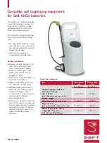
After topping-up of the battery,
the density of the electrolyte is at

its lowest. After consumption of
the electrolyte reserve, the density
of the electrolyte is at its highest.

The construction of a monoblock
does not permit electrolyte
sampling of an STM battery
with integrated ramp without
mechanical destruction of the
monoblock. Measuring the density
of the electrolyte is therefore
impossible. 

!

Separator

The separator of the STM
monoblocks is multilayer, non-
woven and made of
polypropylene. It was selected 
to satisfy the three principal
objectives: to be a good insulator
between the electrodes, to have
the right porosity for excellent
electric performance during
charge and discharge, and
ensure the passage of oxygen
ions during charge to facilitate 
he recombination.

!

Container

The monoblock container and 
the fluid chambers containing 
the cooling liquid, if present, are
made of polypropylene, as are 
the cover and the filling ramp 
that are welded to the container
after the insertion and connection
of the battery plate-group and 
the electrolyte.

Summary of Contents for STM 5-100

Page 1: ...Technical manual installation operation and maintenance for Ni Cd STM MR MRE monoblocks type ...

Page 2: ... 4 1 General description 6 1 4 2 Working principle of a centralized filling ramp 7 2 Precautions and practices 2 1 Transport storage 8 2 2 Water and electrolyte 8 2 2 1 Water quality 8 2 2 2 Harm caused in using sulfuric acid or acidic water 8 2 3 Electrical shocks and burns 9 2 4 Possible dangers of hydrogen 9 3 Installation 3 1 Assembly into batteries 10 3 2 Ventilation and cooling 11 3 3 Assemb...

Page 3: ... 2 Topping up operation 18 7 Repair and overhaul of batteries 7 1 Electrolyte specific density 19 7 2 Reconditioning 19 Appendix 1 STM 5 100 MR G RD equipped 20 Appendix 2 STM 5 100 MRE G RD equipped 21 Appendix 3 STM 5 140 MR G RD equipped 22 Appendix 4 STM 5 140 MR D RG equipped 23 Appendix 5 Accessories for the central filling system 24 Appendix 6 Basic specification for filling circuit hoses 2...

Page 4: ...st performance and a long useful life The instructions are of general validity for batteries in Electric Vehicles Nevertheless every vehicle will have a specific battery that has been adapted to its own mechanical electrical thermal and other characteristics Depending on the referenced model specific instructions might be added to this document For uses other than the ones described in this manual...

Page 5: ...f boric acid Wear base resistant gloves and goggles to manipulate the electrolyte Never use sulfuric acid or acidified water to top up electrolyte as acid even in traces destroys the battery Use tools with insulated handles When batteries or vehicles equipped with STM MR MRE batteries are operated in closed premises natural or forced ventilation is necessary Always respect the applicable safety co...

Page 6: ...ght cause the loss of active materials When a battery is charged or discharged the hydroxide ions OH are transferred from one electrode to the other via the electrolyte The alkaline electrolyte a liquid solution of potassium hydroxide KOH and additives provides the means of transport for the ions It does not participate in the electrochemical reaction Its role in the operation being passive the el...

Page 7: ...nto a perforated nickel plated steel strip Subsequently a multi layer separator is placed between the positive and the negative electrodes to form the plate group Electrolyte The alkaline electrolyte in a nickel cadmium battery is a liquid solution of potassium hydroxide KOH lithium hydroxide LiOH or sodium hydroxide NaOH into distilled or demineralized water During the electrochemical reactions t...

Page 8: ...46 282 244 width 120 123 153 153 height 260 260 260 260 Electrolyte reserve 175 175 160 160 cm3 Terminal M 8 x 1 25 M 8 x 1 25 Refer to attached diagram 1 3 Electrical characteristics STM 5 100 MR and MRE STM 5 140 MR Rated capacity IEC 100 Ah 136 Ah C 3 Nominal voltage Un 6 V 6 V Apparent internal resistance completely charged at 20 C 4 mΩ 4 mΩ ...

Page 9: ...When topping up of the battery is necessary water filling is done from a reservoir that feeds the battery with a low pressure pump or through gravity The topping up is being effected cell by cell to a predetermined level The filling of an hydraulic system is completed when all batteries are filled and water appears at the end of its hydraulic system The filling of a battery is completed when all c...

Page 10: ...es through the exhaust tube 5 The lower edge of the gas exhaust tube 5 settles the expected electrolyte level of the cell When the electrolyte reaches this level the remaining air in the cell can no longer escape through the gas exhaust tube 5 and the water reserve generated by the plunging siphon 6 ensures a safe obstruction of the gas inside the cell When the filling of the cell is finished the ...

Page 11: ...vercharges in adjusting the levels regularly see chapter 6 2 If monoblocks have lost their electrolyte by accident drop spills mishandling etc it may be necessary to replenish the electrolyte This can only be done in a Saft factory by Saft specialists Please contact us without fail Measuring the electrolyte specific density The low maintenance STM monoblocks that are equipped with a centralized fi...

Page 12: ...pment 2 4 Possible dangers through hydrogen Low maintenance STM monoblocks are connected in hydraulic series The hydraulic circuit exhausts oxygen and hydrogen gases that are produced during overcharge The hydraulic system can contain highly explosive gases at any moment All interventions on the battery require particular attention to prevent of any kind of leakage If a leak is detected it must be...

Page 13: ...ent protection against deformation of their small sides Only the small sides of the blocks must be braced in case of connection of rows of several monoblocks In practice the monoblock STM 5 140 MR s will be set up in rows on the axis of the small sides without any gap but with a shim plate between the monoblocks The consolidated bracing system must withstand an expansion force of 150 daN per row L...

Page 14: ...ured that no preferential waterflow exists that would cause uneven cooling of the monoblocks When replenishing the cooling liquid care should be taken that no air bubbles form that would cause partial or no cooling at all thus accelerating the aging process or the destruction of the monoblocks or the battery the thermal exchange system of the cooling liquid air is not included in the supplies from...

Page 15: ... connection between two monoblocks use a hose as specified in appendix 6 For distances greater than 200 mm between the battery and the water tank for example or to form a loop use flexible reinforced PVC pipe with a diameter of 10 x 16 mm part number 208 859 For very tight loops it is preferable to use a 90 polypropylene elbow part number 444 103 Avoid any nipping or squeezing of the flexible pipe...

Page 16: ...intenance STM monoblocks are delivered filled and electrically discharged On receipt and or after a storage period a commissioning cycle is required Do not top up with water prior to the first charge even if the electrolyte level is underneath the minimum level or does not show at all After long storage periods the electrolyte can be totally absorbed by the electrodes Individually shipped monobloc...

Page 17: ...below 35 C This means in practice after a discharge it is necessary to take enough time to let the battery cool down to below 35 C before starting the charging operation Charges at higher temperature are always possible but the battery capacity and its useful life will progressively be reduced Nevertheless full capacity will be restored after some full charges at temperatures below 35 C 5 2 Two le...

Page 18: ...itation The charge coefficient is 1 15 The maximum charging time of a fully discharged battery is approximately 8 hours Temperature compensation It is essential that the battery reach the threshold voltage before it is fully charged As the voltage characteristics of Ni Cd batteries vary with their temperature higher voltage when cold and lower voltage when hot it is imperative to correct the volta...

Page 19: ... Correcting factor of the Voltage threshold 10 C x 0 03 V C 0 3 V Voltage threshold for charge at 0 C8 15 V 0 3 V 8 45 V A special document concerning the charging methods recommended by Saft is available on request from the application service 16 STM 5 100 MR and MRE STM 5 140 MR First level Constant current 20 A 28 A 0 2 C5A Voltage threshold 8 15 V monoblock 8 15 V monoblock Time t1 until the v...

Page 20: ...temperature The rated capacity of STM monoblocks is set at 20 C for an end voltage of 5 V In practice STM monoblocks can be very deeply discharged Occasional polarity inversion will not harm the monoblocks However this polarity inversion must remain exceptional to avoid water consumption not taken into account by topping up The table on the right shows general rules and voltages 17 STM 5 100 MR an...

Page 21: ...r a number of cumulated overcharged amperehours according to model STM 5 100 MR et MRE 1 000 Ah overcharged STM 5 140 MR 800 Ah overcharged Topping up operation Topping up must not be carried out during the first 30 minutes after the end of an overcharge 1 but it can be carried out during a peak charge period and after its controlled term 2 Water is filled into the hydraulic system from a reservoi...

Page 22: ...only be done by specialists from Saft 7 2 Reconditioning Reconditioning becomes necessary when the battery capacity is judged as being too low when the battery or the electronics of an electric vehicle have been repaired or when it has lost the battery management information Procedure Commissioning charge at constant current as described in chapter 4 2 STM 5 100 MR 7 A during 21 hours STM 5 100 MR...

Page 23: ...Appendix 1 20 Monoblock STM 5 100 MR G RD equipped Positive left Filling right ...

Page 24: ...21 Appendix 2 Monoblock STM 5 100 MRE G RD equipped Positive left Filling right ...

Page 25: ...Appendix 3 22 Monoblock STM 5 140 MR G RD equipped Positive left Filling right ...

Page 26: ...Appendix 4 23 Monoblock STM 5 140 MR D RG equipped Positive right Filling left ...

Page 27: ...Polypropylene elbow 444 103 hose to hose connection Female connector 280 604 plug normally closed Male connector 280 605 plug normally closed Female connector 280 602 free Male connector 280 603 free Male connector 280 804 free wall penetration Male connector 280 805 self closing wall penetration Appendix 5 24 ...

Page 28: ...W 80 Brake fluid Lead free gasoline Cooling liquid Vaseline Base material Elastomer EPDM all rubber without internal reinforcement Resistivity 106 Ω cm as per ASTM D257 Recommended dimensions for sleeveless connection to monoblock nozzle inside 9 4 0 3 outside 14 1 0 3 Visual No color requirements specified The inside of the hoses must be perfectly smooth to avoid leaks when fitting the hose on th...

Page 29: ...relative pressure 0 500 mbar After pressure cycle verification of tightness at relative pressure of 300 mbar between 30 C and 70 C Base material Elastomer EPDM all rubber without internal reinforcement Resistivity 106 Ω cm as per ASTM D257 Recommended dimensions for sleeveless connection to monoblock nozzle inside 7 0 2 0 3 outside 11 6 0 5 Visual No color requirements specified The inside of the ...

Page 30: ...ase material baseline inspected annealed copper as per chapter 4 2 1 of regulation NF A 51 119 Protection nickel plated adhesion as per chapter 4 2 of regulation NF A 91 101 Recommended cross chapter 40 mm2 16 x 2 5 Boring 8 25 0 2 Appendix 8 27 ...

Page 31: ...rless odorless when boiling Resistivity at 20 C 30 000 Ω cm Chemical Characteristics 5 pH 7 Absence of organic matter and reducing substances COD chemical oxygen demand 30 mg l permanganate test Total ions SO2 CI 10 mg l and CI 2 mg l 4 Dry residue 15 mg l Silicium as SiO2 20 mg l Appendix 9 28 ...

Page 32: ... Fax 33 0 1 49 93 19 50 www saftbatteries com Doc N RM 04 01 21085 2 Informations in this document is subject to change without notice and becomes contractual only after written confirmation by Saft Société Anonyme au capital de 500 000 000 F RCS Bobigny B 383 703 873 CSB Printed in France ...

Reviews: