background image


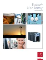
INDUSTRIAL BATTERY GROUP 

Doc Ref: 

ED2015-0544


User’s Manual 

Lithium-ion Battery System (504V / 45 Ah) 


Type of document: 

User Manual 

Created on: 04/12/2015 

This document is 

Saft

 property. Any reproduction, diffusion or communication, even partial, are liable to prosecution without formal authorization. 


Lithium-ion Stationary Battery System 

P/N 777308-00 

BTR-0504V-VL45E-NCA-009M 

504V / 45Ah 


Summary of Contents for 777308-00

Page 1: ...V 45 Ah Type of document User Manual Created on 04 12 2015 This document is Saft property Any reproduction diffusion or communication even partial are liable to prosecution without formal authorizatio...

Page 2: ...2 45 DOCUMENT REVISION Version Date Changes 1 04 12 2015 First issue 9 Synerion modules version based on the ED2014 0210_UM_10 Syn48E battery_rev2...

Page 3: ...in the user and the maintenance manuals are not applied Saft s warranty on the battery is no longer applicable and Saft disclaim any liability for any and all direct indirect or consequential damages...

Page 4: ...e unit to water or condensation Install the batteries in an area compatible with pollution level 2 according to EN 60664 1 typical of office or laboratory environments 4 Do not place the batteries on...

Page 5: ...and Operating instructions 21 4 1 General principle 21 4 2 Safety functions 21 4 2 1 Over charge protection 21 4 2 2 Over discharge protection 22 4 2 3 Over temperature protection 22 4 2 4 Over curre...

Page 6: ...1596 41 15 APPENDIX VI Module to BMM connection drawing 772872 42 16 APPENDIX VII Fault codes and alarm list of the battery system 43 LIST OF FIGURES Figure 1 Synerion 48E module 9 Figure 2 Battery Ma...

Page 7: ...current to the battery Battery Module Management BMU CAN Battery Management Unit Controlled Area Network EDU Electro technical Device Unit EMS EOL HMI HVIL Energy Management System End Of Life Human...

Page 8: ...tle Emitter Reference Rev RD1 CAN OPEN dictionary for BMS SAFT SDU SEL DH 09 0974 L RD2 Diagnostic WinBMS Software User Manual SAFT User_Manual_WinBM S_11 1093 7 RD3 Uninterruptible power systems Elec...

Page 9: ...cepting delivery from the carrier If there is any sign of damage report it to the carrier and to SAFT and make a certified letter with acknowledgement to the transporter For each battery system ensure...

Page 10: ...munication ribbon cables 1 CDROM or USB key with SAFT diagnostic software DiagWinBMS and its User Manual It is advised to save the original packaging for reuse in case of later shipment Termination co...

Page 11: ...al characteristics Power supply characteristics TBTS compliant with CEI_60950 1 touch current 0 25 mA voltage 24 5 Vdc maximum current 1 A maximum power 24 W ripple 100 mV inrush current 700 mA Insula...

Page 12: ...lowing EN50178 1 1997 Environment temperature 5 to 40 C Environment humidity 5 to 85 EMC Following EN 62040 2 C3 for immunity C1 for emissions Electrostatic discharge 4kV contact 8kV air Fast transien...

Page 13: ...max Module 14 cells in series 54V max Module 14 cells in series 54V max Module 14 cells in series 54V max Power supply 24V Module 14 cells in series 54V max BMM RS485 Diagnostic bus 9 modules in serie...

Page 14: ...igital line driven by redundant hardware channel This signal is active in case of Cell over charge Cell over discharge Module over temperature Module switched OFF The electronic board manages also the...

Page 15: ...tion to converter Red point side Yellow point side Figure 6 BMM HMI CAN Communication to EMS RS485 Diagnostic 24Vdc Power supply CAN Communication to SMU Battery converter connection polarity Battery...

Page 16: ...its self test by testing its internal functions During self test the battery will be connected Beware of high voltage The battery communicates by CAN Open protocol At start up the CAN Open node is in...

Page 17: ...ted only after their installation connect them together and to the BMM as shown in the drawing below with the red power cable delivered with module Then connect the modules together and to the BMM wit...

Page 18: ...battery circuit must be kept insulated from the ground Battery polarities must NOT be connected to any part of the chassis or other conductive part Never disconnect power connections under load Inter...

Page 19: ...be 1A 3 8 4 Power supply connector A three contacts male connector ref 1440070 from Phoenix Contact is used to supply the BMM See 2 1 for BMM power supply characteristics Compatible with ref 1681172...

Page 20: ...ors is used for RS485 diagnostic bus This connector is insulated from High voltage by a protective separation Figure 12 Diagnostic connector 1 RS 485_A 2 RS 485_B 3 CAN_L 4 CAN_H 5 GND 0V 6 24Vdc Powe...

Page 21: ...the battery contactor is opened and the battery goes in SAFE mode see 4 5 for mode description the battery will go back in STANDBY mode if critical fault is reset software reset or hardware reset If...

Page 22: ...module temperature 70 C 4 2 4 Over current protection Some kinds of protection are used to protect battery against over current and to prevent cells ageing by optimizing charge and discharge current...

Page 23: ...ftware at least revision 2 9 5 Refer to document RD2 and 4 6 8 One dedicated software DiagWinBMS installed on a computer compatible using an external USB RS485 converter is used to Monitor the battery...

Page 24: ...t ok the BMM will go in SAFE state The self test duration is roughly 6 seconds Stand by in this mode the battery pack is not yet operating BMU is waiting from EMS for the permission to close the conta...

Page 25: ...who can or not reset them or if the fault condition is no more present for some kind of alarms Transition between modes States transition Conditions 1 Off Init BMM is supplied with 24Vdc 2 Init Stand...

Page 26: ...parameters o Battery temperature o Battery SOC IMR_C is decreased to 50 between 85 SOC to 100 SOC Figure 14 IMR IMR_C versus SOC profile 4 8 Charge profile description The charge consists in a CC CV C...

Page 27: ...g and decreases the IMR current until IMR_C value the slope will depend on the current value and the time above the limit about 30s for high current The contactor will open if the current is upper the...

Page 28: ...ell voltage is below 3 325V during 2 hours see 4 5 the BMM will automatically put the system in SLEEP state To restart the system when it is in SLEEP state send a RESET frame by CAN bus which is still...

Page 29: ...voltages target transmitted permanently via the internal CAN bus Balancing operates in all states when the BMM is power supplied During storage without BMM connected or with BMM powered off the balan...

Page 30: ...302h Byte0 0 N U Byte1 0 N U Byte2 2055h Battery contactors authorization Byte3 0 N U Byte4 0 N U Byte5 0 N U Byte6 0 N U Byte7 0 N U Byte2 Bit0 Authorization for Main contactor 0 not authorized to cl...

Page 31: ...equest For details see document RD1 Time stamp object In order to time stamp data inside the black box Time stamp object 1012h need to be sent at least one time at each BMM start up 4 15 SOH and EOL d...

Page 32: ...rence between the cells balancing efficiency is 25mV per day for VL45E in average depending on cell voltage For example if a battery is stored during one year the battery balancing can take up to 20 d...

Page 33: ...ge sent the modules can be stored at least 4 months After this period recharge the module with an adapted equipment see 6 2 3 6 2 3 Battery recharge in storage Modules can be recharged individually on...

Page 34: ...f the modules have been exposed to abnormal conditions crushes short circuit overcharge overheat electrolyte leakages on cells contact SAFT Do not open the modules and BMM It is the responsibility of...

Page 35: ...ged in the transport of dangerous goods shall receive training in the contents of dangerous goods requirements commensurate with their responsibilities Refer to UN regulations for more details 8 3 Bat...

Page 36: ...erminals or the unit s It is recommended to individually pack each unit in a plastic bag do not store close to a heat point keep the packaging in a dry place use a strong packaging to handle the weigh...

Page 37: ...44 User s Manual Lithium Ion Battery System 504V 45Ah 37 45 This document is Saft property Any reproduction diffusion or communication even partial are liable to prosecution without formal authorizati...

Page 38: ...544 User s Manual Lithium Ion Battery System 504V 45Ah 38 45 This document is Saft property Any reproduction diffusion or communication even partial are liable to prosecution without formal authorizat...

Page 39: ...ser s Manual Lithium Ion Battery System 504V 45Ah 39 45 This document is Saft property Any reproduction diffusion or communication even partial are liable to prosecution without formal authorization 1...

Page 40: ...s Manual Lithium Ion Battery System 504V 45Ah 40 45 This document is Saft property Any reproduction diffusion or communication even partial are liable to prosecution without formal authorization 13 A...

Page 41: ...s Manual Lithium Ion Battery System 504V 45Ah 41 45 This document is Saft property Any reproduction diffusion or communication even partial are liable to prosecution without formal authorization 14 A...

Page 42: ...s Manual Lithium Ion Battery System 504V 45Ah 42 45 This document is Saft property Any reproduction diffusion or communication even partial are liable to prosecution without formal authorization 15 AP...

Page 43: ...HW ON OFF Reset Client Auto reset 4 A module is over temperature Module temperature 60 C during 2s HW ON OFF Reset Client Auto reset Contactor opening 5 A module is going under temperature Module tem...

Page 44: ...battery current MAX 1 6 x IMR 55A during 30s HW ON OFF Reset Client Contactor opening 20 Over current in discharge Measured battery current MAX 1 1 x IMD 55A during 30s HW ON OFF Reset Client Contacto...

Page 45: ...OFF Reset Client Auto reset 38 Low SMUs supply voltage Default on V_POWER_SMU HW ON OFF Reset Client Auto reset Contactor opening 39 Unbalanced cells Delta cell voltage over all the module 100mV durin...

Reviews: