


DOK451 rev.2
Page 21 of 26
Service mode is entered by clicking on the Service mode tab next to the Normal mode tab after the gyro module has
been powered up. Service mode usage, functionalities and descriptions are listed in Table 5. Exit from Service mode
to Normal mode by selecting one of the other panel tabs (Normal, Logging, Service or Parameter panel tab).
Note: Changes made for the gyro module in Service mode are only stored permanently in flash memory when the
save command (‘s’) subsequently is sent to the gyro module.
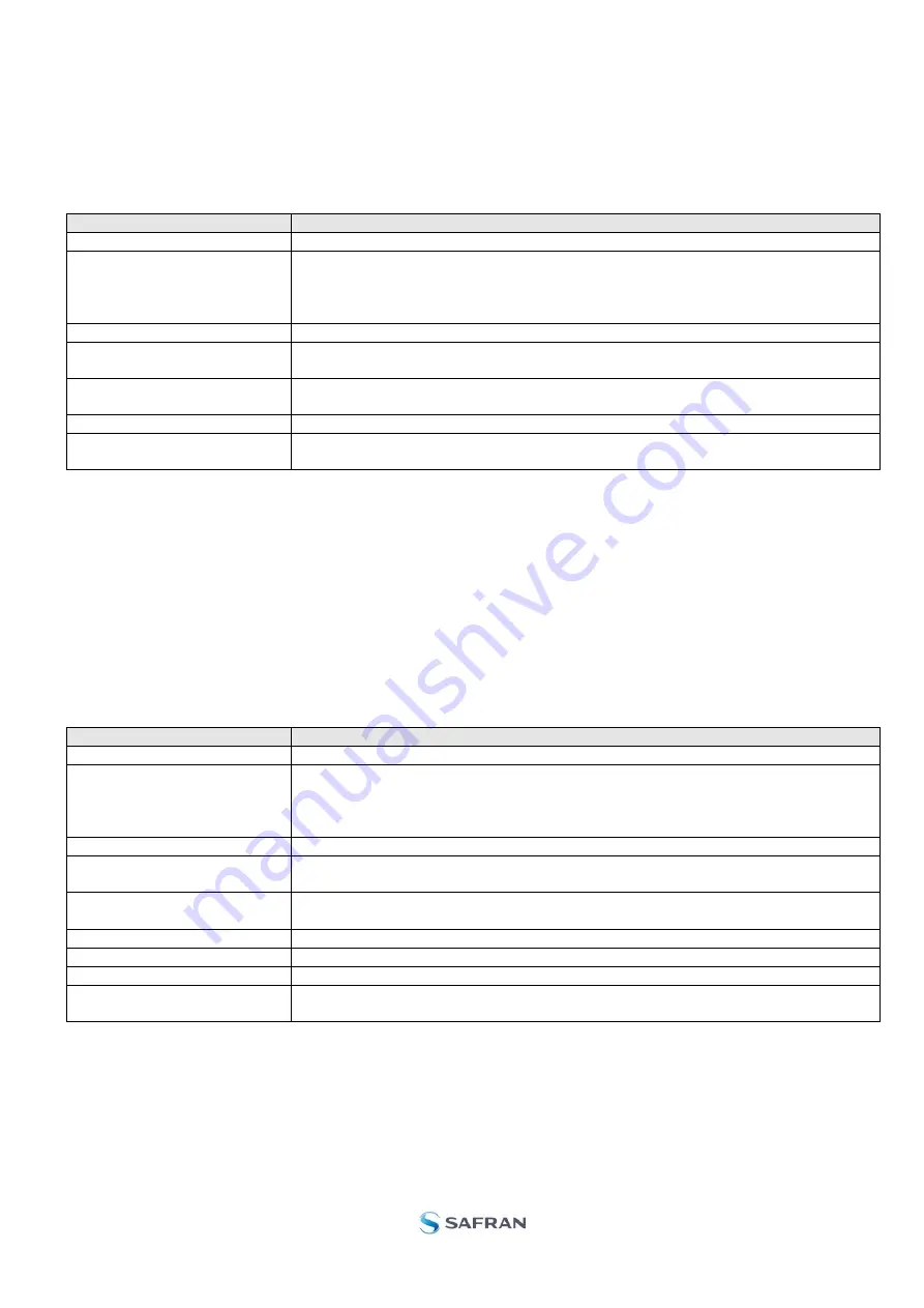
Panel content
Functionality and description
Available commands window
Shows a list of available commands. See product datasheet for details
Complete command window
Contains the complete command to be sent. The command is auto-completed by
the software during usage of the listings in the Available commands window. Left
click inside the Complete command window brings up a list of previously sent
commands. Right click enables manual command entry
Send command button
Sends command to the gyro module
Active device indicator
Indicates active gyro module. Corresponding COM port is specified in the active
parameter file
Command response window
Shows the responses to commands from the gyro module. See product datasheet
for details
Erase button
Clears the content of the command response window
Save button
Saves the content of the command response window to a text file with a date and
time tag
Table 5:
Service mode panel descriptions
7.5
Utility mode panel
Utility mode is used for gyro module configuration and supports the same functionality as the Service mode, however,
the protocol is optimized for machine-to-machine communication.
Utility mode is entered by clicking on the Utility mode tab next to the Service mode tab after the gyro module has been
powered up. Utility mode usage, functionalities and descriptions are listed in Table 6. Exit from Service mode to
Normal mode by selecting one of the other panel tabs (Normal, Logging, Service or Parameter panel tab).
Note: Changes made for the gyro module in Service mode are only stored permanently in flash memory when the
save command (‘s’) subsequently is sent to the gyro module.
Panel content
Functionality and description
Available commands window
Shows a list of available commands. See product datasheet for details
Complete command window
Contains the complete command to be sent. The command is auto-completed by
the software during usage of the listings in the Available commands window. Left
click inside the Complete command window brings up a list of previously sent
commands. Right click enables manual command entry
Send command button
Sends command to the gyro module
Active device indicator
Indicates active gyro module. Corresponding COM port is specified in the active
parameter file
Command response window
Lists the responses to commands from the gyro module. See product datasheet for
details
Command w. CRC window
Show last sent command with CRC
Response w. CRC window
Shows received response to last command with CRC
Erase button
Clears the content of the Command response window
Save button
Saves the content of the Command response window to a text file with a date and
time tag
Table 6:
Utility mode panel descriptions


