mRO Evaluation Kit User Manual
Page 1 of 16
Revision: 1
12 December 2023
ELECTRONICS & DEFENSE
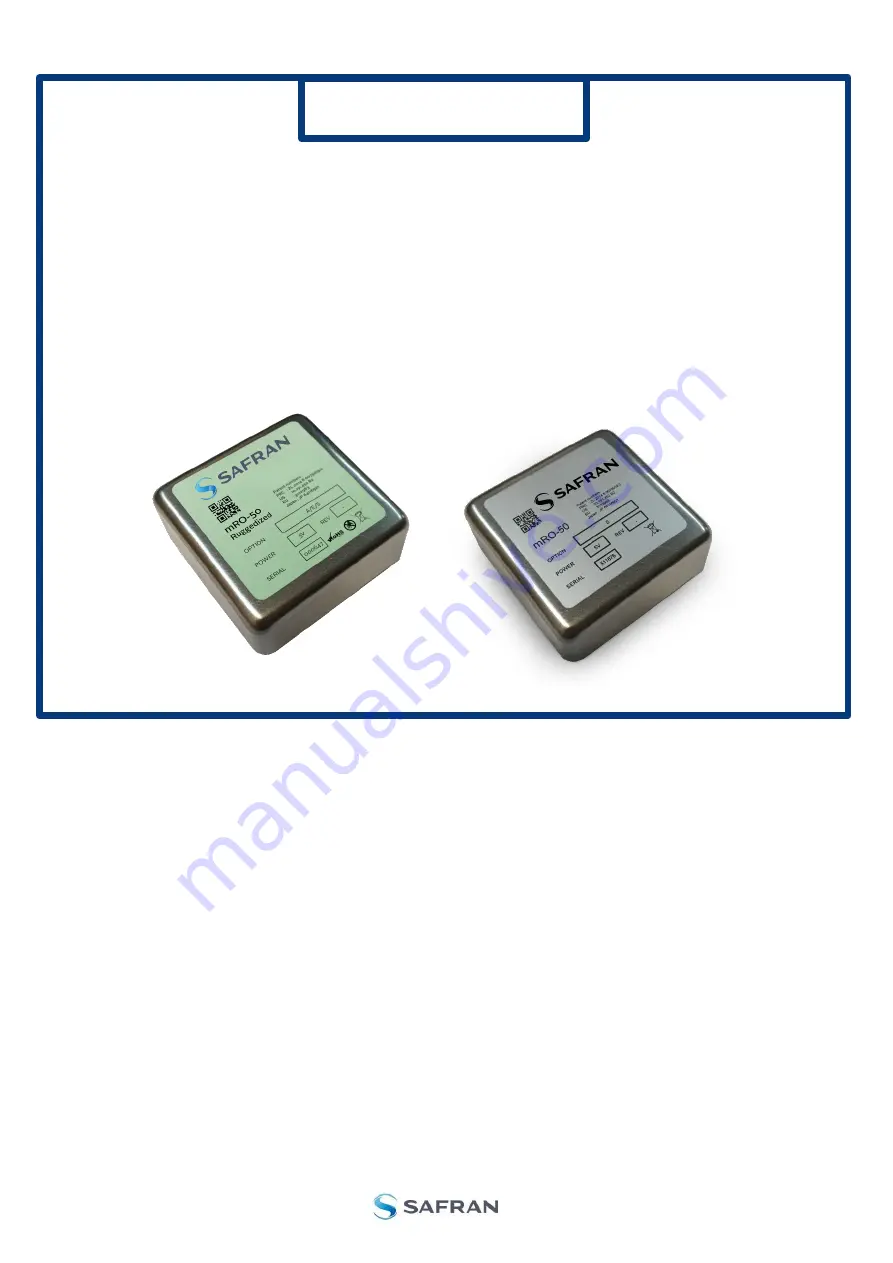
MRO
SERIES
Evaluation Kit Manual
Page 1: ...mRO Evaluation Kit User Manual Page 1 of 16 Revision 1 12 December 2023 ELECTRONICS DEFENSE MRO SERIES Evaluation Kit Manual...
Page 2: ...aluation board with mRO A Power supply with stabilized power unit 7Volts B Power selector give the ability to supply the mRO with a stabilized power supply unit A or from an USB PORT C coming from a p...
Page 3: ...all cables are properly connected The equipment contains small quantities of rubidium metal hermetically sealed inside the glass lamp and cell assemblies hence any dangers arising from ionizing radia...
Page 4: ...up to 20s to execute and open the Settings window Settings window Select the available COM port connected to the evaluation board and press Connect Connect button The software will automatically detec...
Page 5: ...voltage control input 11 CFIELD micro Amp current flowing through the magnetic coil in micro Amp 12 Temperature cell setting int temperature setting point of the Rb Cell 13 Temperature laser setting...
Page 6: ...ntacted according to the Timegate parameter configured in seconds Timegate selection The mRO memory can be recorded inside a dedicated mRO parameters file Select Save to record these parameters Memory...
Page 7: ...urement Monitor window When the start button has been selected data monitoring will plot to a graph in the Measure window Measurement ON At the bottom left monitor box the status of the commands sent...
Page 8: ...r diode MON Laser PIL is the laser diode voltage MON TPCB is the temperature of mRO PIL DAC VC for the mRO 50 is the 10 MHz TCXO voltage control input which drives the atomic clock PIL DAC VC 16 for t...
Page 9: ...t the heating used by the heating system in order to warm the laser diode 5 Heating Power the total power dedicated to warm the laser diode 6 Servo loop the Padlock shows the state of the laser loop V...
Page 10: ...ncy adjustment 2 Pil CField is the setting value of the power stage which drives the current flowing through the magnetic coil 3 Current is the current value of the magnetic coil 4 Servo loop is the s...
Page 11: ...window gives the ability to the mRO to lock automatically on the Rb line after power ON Command window 5 3 2 Cell temperature window The Cell temperature window set the temperature of the Rb cell is...
Page 12: ...utput due to the high quality factor of the atomic loop The PLL modulator can set the mRO frequency output in a range of 9 999 995 00 to 10 000 005 00 Hz 500 ppb without any stability degradation Sele...
Page 13: ...hermal compensation loop can be opened without any condition 10 minutes after Power ON The Atom loop can be opened without any condition 10 minutes after power ON It is not recommended to open the Las...
Page 14: ...lect a path in order to save all parameters of the mRO and press Start Firmware update window Firmware update ongoing firmware is written inside the microprocessor It takes around 4 minutes maximum to...
Page 15: ...For technical support product specifications and additional documentation you can visit https safran navigation timing com support hub mro 50 support hub to submit a support request More information...
Page 16: ...No license is granted by implication or otherwise under any patent or patent rights of Safran Trademarks and registered trademarks are the property of their respective owners Safran products are not...