


User Manual
V1.7 2019 Copyright SafeWaze
Page 19
13.0 Labels
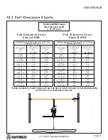
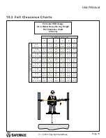
WARNING
This clearance chart
only applies to
Horizontal Lifeline
systems installed at
or above Dorsal
D-ring Height, with
users connected to
the HLL System with
a 6 ft. Energy
Absorbing Lanyard.
For additional
information see
User’s Manual.
10
5
10
15
20
25
30
35
40
45
50
55
60
65
70
75
20
30
40
50
60
70
80
90
100
CLEARANCE CHART
SPAN LENGTH (FT)
RE
Q
UI
RE
D
VE
RT
IC
AL
C
LE
AR
AN
CE
019700
1 User 6’
EAL
2 Users 6
’ EAL
1 Class A SRL
2 Class A SRL
2 Class B SRL
1 Class B SRL
(30’) 2 PERSON TEMPORARY KERNMANTLE
HORIZONTAL LIFELINE SYSTEM
MFG DATE:
PART NUMBER:
019-8004
SERIAL NUMBER:
XXXXXXX
XX/XX
WWW.SAFEWAZE.COM
019720
BARCODE
WARNING
Manufacturer’s instructions supplied with this product at time of shipment must be
read and understood prior to use. Ensure Horizontal Lifeline is installed at an
elevations which will limit Free Falls to a maximum of 6 feet when using Energy
Absorbing Lanyards, and installed overhead when using Self Retracting Lifelines.
This equipment must be installed under the supervision of a Qualified Person.
Inspect all connections prior to use and verify connecting components are installed
correctly. Failure to make secure connections could result in serious injury or death.
Not flame or heat resistant. Avoid contact with sharp and abrasive edges. Caution
should be taken using this equipment near Hazardous Thermal, Electrical, or
Chemical Sources. Equipment exposed to fall arrest forces should be immediately
removed from service. Alteration or misuse of this product, or failure to follow
instructions could lead to serious injury or death. DO NOT REMOVE THIS LABEL.
019702
INSPECTION:
SYSTEM MUST BE INSPECTED
PRIOR TO EACH USE TO DETERMINE IF IT IS IN
GOOD WORKING CONDITION WITH ALL SYSTEM
CONNECTIONS PROPERLY SECURED. THE
SYSTEM SHOULD BE INSPECTED AT LEAST
MONTHLY BY A COMPETENT PERSON OTHER
THAN THE USER. IF INSPECTION REVEALS A
DEFECTIVE OR UNSAFE CONDITION, THE
SYSTEM MUST BE REMOVED FROM SERVICE.
THIS SYSTEM IS NOT USER REPAIRABLE.
019703
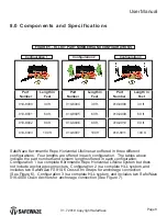
SPECIFICATIONS:
THIS HORIZONTAL LIFELINE
SYSTEM IS DESIGNED FOR USE BY UP TO TWO
WORKERS. MAXIMUM WEIGHT FOR EACH WORKER
INCLUDING TOOLS AND EQUIPMENT IS 310 LBS.
MATERIALS:
Rope: Polyester Cover, Nylon Core
Rope Tensioner: Steel
Anchor Straps: Polyester
Hardware: Steel
THIS HLL SYSTEM MEETS OSHA REQUIREMENTS
FOR FALL PROTECTION WHEN USED AS DEFINED IN
THE USER’S MANUAL
019706
019718
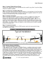
Typical Installation
Max. 100 Ft Span Length
In -Line Shock Absorber
Cross-Arm Strap
Attachment O-Ring for User (Lanyard)
Anchorage
Carabiner
Rope Tensioner
Rope
Typical Installation
Max. 100 Ft Span Length
In -Line Shock Absorber
018-4000 Chain Anchor
Attachment O-Ring for User (Lanyard)
Anchorage
Carabiner
Rope Tensioner
Rope
J
J J
F M A
A S O N D
M
Inspection Log
Do Not Remove Label
019704