background image

17

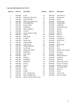
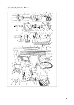
Spare parts & Exploded view of ST.33

Drawing

Article nr.

Description

Drawing

Article nr.

Description

1

360.1001

Screw

34

360.1034

Pressing strip

2

360.1002

Motorhousing left side

35

360.1035

Wiring cover

3

360.1003

Label (Left side)

36

360.1036

Frame

4

360.1004

Motorhousing right side

37

360.1037

Clampsystem

5

360.1005

Label (Right side)

38

360.1038

Setting Screw

6

360.1006

Sensor Holder

39

360.1039

Setting Nut

7

360.1007

Bolt M5x60

40

360.1040

Motorcable cover

8

360.1008

Motor Assembly

41

360.1041

Wire #1

9

360.1009

Pin 6x60

42

360.1042

Wire #2

10

360.1010

Lower Inner Gear Plate

43

360.1043

Wire #3

11

360.1011

Gasket

44

360.1044

Wire #4

12

360.1012

Bearing 608

45

360.1045

Connector

13

360.1013

1st Gear

46

360.1046

Coupling nut

14

360.1014

Spindle Gear

47

360.1047

Capstan hub

15

360.1015

Bearing 626ZZ

48

360.1048

Arm

16

360.1016

Adaptor ring

49

360.0001

Battery Pack

17

360.1017

Bearing 6003DDU

50

360.1050

Bolt

18

360.1018

Gear Casing

51

360.1051

Screw

19

360.1019

Spindle Drive Shaft

52

360.1052

Battery Contact board

20

360.1020

Bolt M5x10

53

360.1053

Connector

21

360.1021

Tank holder

54

360.1054

Connector

22

360.1022

Slide

55

360.1055

Battery slide base

23

360.1023

Washer 6

56

360.1056

On Switch

24

360.1024

Bolt M6x20

57

360.1057

Off Switch

25

360.1025

Bolt M6x14

58

360.1058

Main power Switch

26

360.1026

Steady

59

360.1059

 connector

27

360.1027

Spindle

60

360.1060

 connector

28

360.1028

Rack

61

360.1061

Front Panel Plate

29

360.1029

Screw

62

360.1062

Crimp nut

30

360.1030

Washer

63

360.1063

Screw

31

360.1031

Brass rail (Left side)

64

360.1064

Control Unit

32

360.1032

Brass rail (Right side)

65

360.1065

Rear Panel Plate

33

360.1033

Motor cable protection screw

Summary of Contents for ST.33

Page 1: ...1 IN 365 03 USER MANUAL ST 33 ...

Page 2: ...l cutting tools and products to help you be more productive Before operating your new drilling machine please read all instructions first These include the Operator s Manual and Warning Label on the unit itself With proper use care and maintenance your model will provide you with years of effective hole drilling performance TO REDUCE THE RISK OF INJURY USER MUST READ AND UNDERSTAND ALL INSTRUCTIONS...

Page 3: ...irectives of the European Community Class of protection I Product with basic insulation and exposed touchable conductive parts additionally connected to the protective earth conductor mm Millimeter Unit of measure for length width height or depth kg Kilogram Unit of measure for the mass V Volt Unit of measure for the electric voltage A Ampere Unit of measure for the electric current intensity W Wa...

Page 4: ...y drilling machine Distractions can cause you to lose control 4 Do not expose drilling machines to rain or wet conditions PERSONAL SAFETY 1 Stay alert watch what you are doing and use common sense when using a drilling machine Do not use machine while tired or under the influence of drugs alcohol or medication A moment of inattention while operating magnetic drilling machines may result in serious...

Page 5: ...hildren and other untrained persons Tools are dangerous in the hands of untrained users 7 Maintain machines with care Keep cutting tools sharp and clean Properly maintained tools with sharp cutting edges are less likely to bind and are easier to control 8 Check for misalignment or binding of moving parts breakage of parts and any other condition that may affect the machine operation If damaged hav...

Page 6: ...piece while the machine is turned on Before turning on the machine make sure the accessory has been mounted correctly Do not use the machine on the same work piece on which electric welders are being used Use only an appropriate cutting fluid Use a general non oil based metal cutting coolant diluted with water Do not use liquid cutting fluids while drilling vertically or overhead Dip the cutter in...

Page 7: ...turing and identification number is engraved on the frame and the motor unit Example 360 12 11 001 Model type Year of Manufacture Month of manufacture Identification number Package Contents The package contains 1 Drilling machine 1 Battery pack 37 V 10 5 Ah 1 Carrying case 2 Rail profiles for std rails 3 Handles 1 Allen Key 2 5 1 Allen Key 4 1 Allen Key 5 1 Wrench 8 1 Lubrication system 1 Drill ch...

Page 8: ...d vibration Two figure specifications as per ISO 4871 Sound emission Measured A weighted sound power level LwA re 1 pW in decibels 89 Measuring uncertainty KwA in decibels 3 A weighted emission pressure power level measured at the workplace LpA re 20 μPa in decibels 89 Measuring uncertainty KpA in decibels 3 Vibration emission Rated acceleration in m s 0 5 Measuring uncertainty K in m s 1 5 REMARK...

Page 9: ...es or slightly damaged components to ensure they are operating perfectly and as intended Check that moving are in perfect working order and do not jam and check whether parts are damaged All parts must be correctly installed and fulfill all conditions necessary to ensure perfect operation of the machine Damaged protective devices and parts must be repaired or replaced according to specifications b...

Page 10: ...attery quicker INSERTING AND REMOVING AN ACCESSORY Remove the battery pack from the machine before any adjustments conversions or servicing are performed Do not use deformed or damaged tools Before use always check tools such as core drills for deformities or damage Do not use accessories that have not been specified or recommended by Safetrack for this machine The ability to attach the accessory ...

Page 11: ...g and allow it to run at full speed 5 Turn the arms to start drilling Apply only a slight pressure when the Annular Cutter touch the metal Do not push the TCT Cutter with force into the metal 6 Apply a regular pressure while drilling The drilling performance does not improve by putting more pressure on the feed handles Too much pressure will overload the motor and your Annular Cutter will break or...

Page 12: ... lubricated periodically with grease to ensure smooth operation Raise the motor unit to the highest position possible Lubricate the dove tail guide way at both sides Lubricate the gear rack After repeated use the gear rack may become loose If necessary adjust the 5 self locking set screws at the left side Tighten screws in series until the gear rack moves freely in the dove tail guide but does not...

Page 13: ...hecked before operation for any signs of damage that will affect the operation of the machine Particular notice must be taken of the mains cable if the machine appears to be damaged it should not be used failure to do so may cause injury or death CAUTION Clean all dirt dust metal chips and burrs of your drilling machine OPERATION OF THE MACHINE The machines operation must be checked to ensure that...

Page 14: ...ting nuts and screws 3 Operate the slide up and down a few times to test the movement and make any further necessary adjustments Try to ensure that all the screws are exerting a uniform pressure on the slide from top to bottom A perfectly adjusted slide will operate freely up and down without any sideways movement REPAIR MODIFICATION AND INSPECTION Repair modification and inspection of Safetrack d...

Page 15: ...out No grease in gear box Motor humming big sparks and motor has no force Armature damaged burned Field burned Motor does not start or fails Damaged or defective wiring Dirt in sensor Speed Control Unit Damaged or defective sensor Speed Control Unit Damage to Armature or field coil Guiding takes a great deal of effort Guide is set too tight Guide is dry needs to be greased Guide gear rack rotation...

Page 16: ...h household waste Make this product available for separate collection Separate collection of used products and packaging allows materials to be recycled and used again Re use of recycled materials helps prevent environmental pollution and reduces the demand for raw materials Local regulations may provide for separate collection of electrical products from the household at municipal waste sites or ...

Page 17: ...indle Gear 47 360 1047 Capstan hub 15 360 1015 Bearing 626ZZ 48 360 1048 Arm 16 360 1016 Adaptor ring 49 360 0001 Battery Pack 17 360 1017 Bearing 6003DDU 50 360 1050 Bolt 18 360 1018 Gear Casing 51 360 1051 Screw 19 360 1019 Spindle Drive Shaft 52 360 1052 Battery Contact board 20 360 1020 Bolt M5x10 53 360 1053 Connector 21 360 1021 Tank holder 54 360 1054 Connector 22 360 1022 Slide 55 360 1055...

Page 18: ...18 Spare parts Exploded view of ST 33 ...

Page 19: ...100 C 212 F If an exposed lithium ion battery does start a fire it may burn even more violently if it comes into contact with water or even the moisture in the air DO NOT THROW WATER ON A BURNING LI ION BATTERY A class C fire extinguisher must be used Do not use the Battery Pack if the Battery Pack casing is broken or if a Battery Pack emits an unusual odor smoke or excessive heat or leaks any sub...

Page 20: ...l the battery pack is depleted If depleted the battery pack will begin charging when placed on the lithium ion charger TO CHARGE A fully discharged battery pack with a temperature between 0 32 F and 65 150 F will charge in about an hour Use battery pack only with the recommended Safetrack charger Connect the charger to a power supply Make sure the power supply is normal household voltage 240 volts...

Page 21: ...dling of these batteries especially when wearing rings and jewelry could result in a serious burn To obtain the longest possible battery life from RIDGID lithium ion batteries we suggest the following Remove the battery pack from the charger once it is fully charged and ready for use For battery pack storage longer than 30 days Store the battery pack where the temperature is below 25 C and away fr...

Page 22: ... signals the RED and GREEN light are simultaneously lit RED and GREEN The charger will start charging again if the temperature of the battery is 45 or less Over temperature recovery SIGNALS ON THE MACHINE Signals well functioning drilling machine When the ST 33 drilling machine is well positioned on the work piece press the main power white switch to on the machine The LED will flash 2x GREEN and ...

Reviews: