


LMU Controller
© Safe Fleet | March 2019 | All rights reserved | Part #: 700-1132 R3
p. 8
Installation
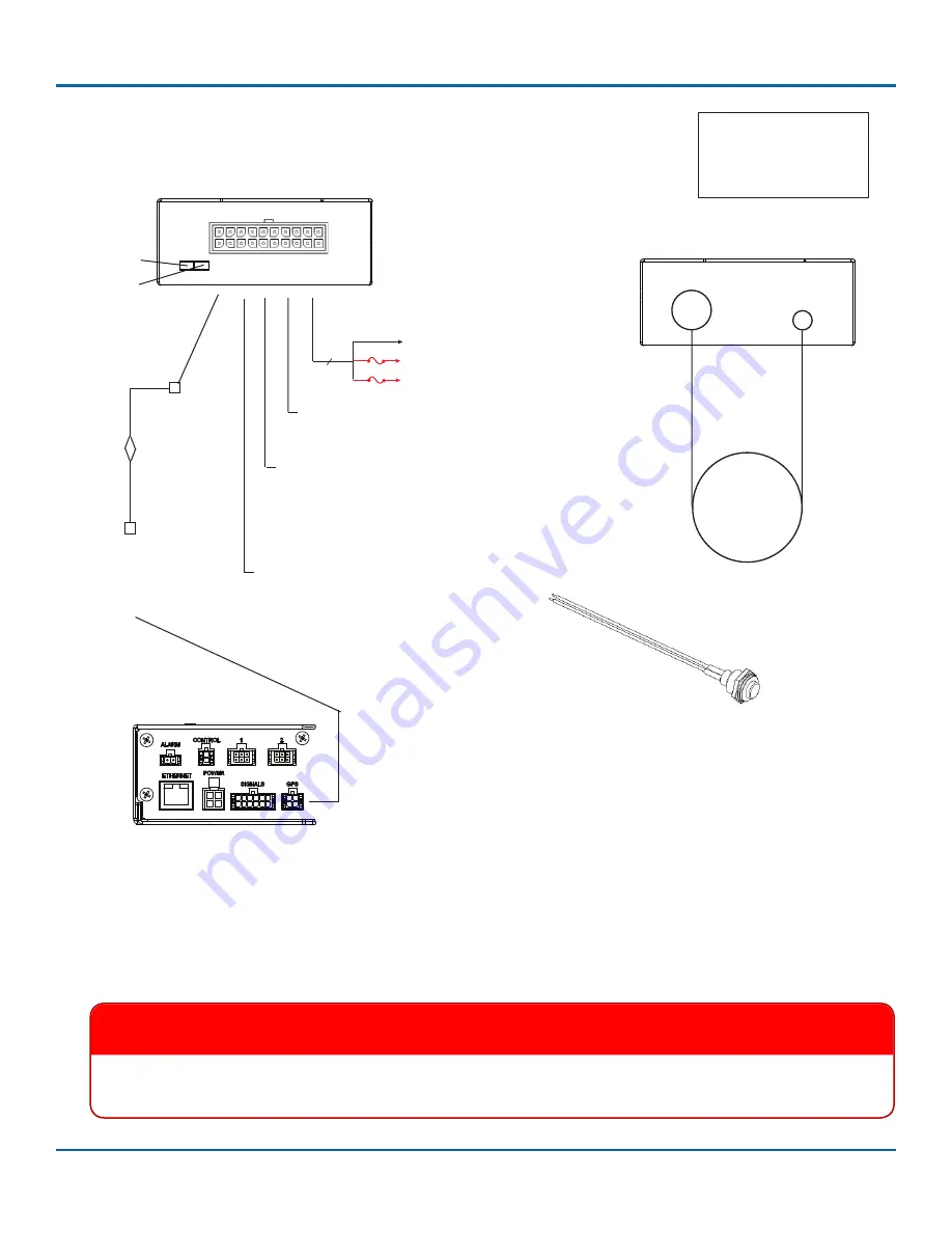
3 wires
3A
Battery Negative (black)
V 12/24V (red)
Black wire from pin 16 to black on
extension cable and Alarm button.
Aux 1
Cable Harness
and Connector
TL/TX/TH/NH16
GPS socket
LMU Controller Connections
Typical System Setup, with optional DVR Connections
Ignition (white)
3A
LMU
to GPS
Adaptor
Cable
Power harness (red, black, white wires)
LMU Controller, Harness LED end
Comm LED
GPS LED
1x5 Microfit
connector
2x2 Microfit
connector
To
DVR
option
Pin 1
Pin 11
Pin 10
Pin 20
NOTE: Aux 2 connector
and other harness
wires not mentioned
here are not used
.
GPS4 Cable
Pin 16 Alarm Button
(black wire, active low)
Pin 3 Stop Arm
(blue wire, active high)
3.5 mm
GPS
Connector
GPS &
Cellular
Antenna
LMU Controller, Antenna end
2.5 mm
Comm
Connector
MX/DX:
GPS socket
on Smart-Link
Orange wire from pin 12 to red on
extension cable and Alarm button.
Pin 12 Alarm Button
(orange wire, active low)
6.
Clip the 1x2 Microfit connector from the end of the alarm button extension cable.
7.
Connect the alarm button’s red and black wires to the extension cable’s red and black wires with the supplied crimps.
8.
If the LMU Controller is being connected to a DVR, connect the AUX 1 connector from the LMU Controller 20 pin
harness to the supplied 060-1012 adapter cable, which connects to the GPS Extension cable, which connects to the
DVR’s GPS socket.
IMPORTANT
If the DVR has a GPS4 unit installed, the GPS4 unit can be removed.
The LMU Controller replaces GPS4
functionality on the DVR.


