SAF-HOLLAND SK RB 9019 W Maintenance And Repair Manual Download Page 6

6

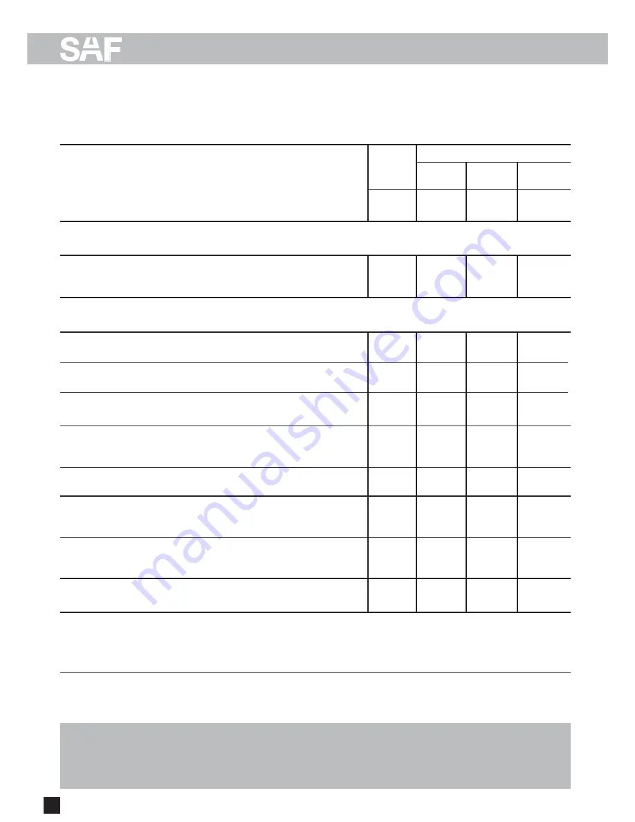
B) Maintenance instructions

SK 1000 Disc / ET 120

SK RB 9019 W - SK 1000 ET 120

Vehicles with long standing periods:

service at specified time intervals

Vehicles used under extreme conditions:

shorten the service interval to 6 months / 

e.g. construction site operation, multi-shift operation

75,000 km

Maintenance intervals

whichever comes first

Mileage intervals

>

Time intervals

>

After first

5,000 km

or

every

30,000 km

every

150,000 km

After first

month

every

3 months

every

75,000 km

every

6 months

every

12 months

Periodic checks

Hub unit maintenance-free.
Visual inspection for grease leaks. 

Inspect the brake caliper guide system.
Check for free movement and sliding action.

Check rubber dust covers for cracks and damages.
Check adjuster cap for correct seating.

Inspect the brake pad thickness 
at regular intervals (e.g. when ever tyre pressure is checked) 
but at least every 3 months.

Inspect the brake disc for cracks.

–  Perform general annual inspection

(brakes, air bags, tyres, etc.)

–  Perform general annual safety check

(tractor/ (semi-) trailer brake compatibility, ABS etc.)

Note:

Be sure to retighten wheel nuts to the 

prescribed torque after the first 50 km and 150 km 
(and after every wheel removal).

Mechanical check

Visual and safety inspection 

Special service conditions

Warranty claims will only be accepted as long as the operating and maintenance instructions
have been complied with and if SAF approved spare parts have been fitted.

NOTE!

If the sealmark on the hub nut is broken before the end of the 1,000,000 km this will
invalidate all warranty coverage unless the repair works have been carried out in an 
SAF-authorised workshop.

Summary of Contents for SK RB 9019 W

Page 1: ...SK RB 9019 Wwith WABCO brake calliper SK 1000 ET 120 Maintenance and Repair Manual for SAF Disc Brakes Service Edition 01 2006...

Page 2: ...fication serial no refer to the axle type plate Please enter the vehicle identification figures in the type plates shown below so that correct information is available when required 2 Vehicle informat...

Page 3: ...and repair A General safety instructions 5 E Service tools 28 F Tightening torque in Nm 29 The item numbers indicated are given only for identification and to distinguish between different versions U...

Page 4: ...NOTIZEN NOTES NOTE 4...

Page 5: ...t overheated by continuous operation With drum brakes overheating can result in a hazardous deterioration in the braking efficiency With disc brakes overheating can result in damage to surrounding com...

Page 6: ...amages Check adjuster cap for correct seating Inspect the brake pad thickness at regular intervals e g when ever tyre pressure is checked but at least every 3 months Inspect the brake disc for cracks...

Page 7: ...uller for Hub Unit 4 434 3822 00 Tool box compl 3 434 6010 00 3 4 spanner external torx shape 4 434 3824 00 Thickness of brake disc A Wear limit of brake disc B NOTE Failure to observe these instructi...

Page 8: ...see page 19 Check adjuster see page 9 END Check brake calliper bearings and repair if necessary see page 18 END END Adjuster OK see page 9 END Replace brake calliper see page 26 END Binding not due to...

Page 9: ...g adjustment Note As the number of rotation steps of the ring spanner increases the turn angle or movement of the SAF ratchet wrench becomes smaller If the SAF ratchet wrench rotates as described abov...

Page 10: ...n the residual lining thickness is A 2 mm replace the brake pads Signs of wear Wear on the middle of the lining can be measured with a tape measure or a ruler either at the shoulder bolt long bolt nea...

Page 11: ...ture cannot enter the inside of the brake cal liper through the brake cylinder connection Painting instructions During painting work all rubber parts must be covered as otherwise the rubber will becom...

Page 12: ...120 SK RB 9019 W SK 1000 ET 120 Torque wrench settings Use a torque wrench The use of impact wrenches is not accepted Wheel nuts Spigot hub centred fixing M 22 x 1 5 600 Nm U bolts diagonally in three...

Page 13: ...nings 64 2 Lining retainer springs 070 Guide pin group including items 70 1 70 6 80 83 78 ABS sensor 080 Guide pin group folding bellows including items 80 80 1 80 3 83 Repair kits for SAF disc brakes...

Page 14: ...nuts and remove the wheel Remove the cap Return adjuster clockwise turn until the stop Loosen and remove the fixing screws of the lining retainer hoop Move the brake calliper towards the rim and remov...

Page 15: ...ls Screw in the tappets again completely Replacing the brake disc Unscrew bolts M 18 x 1 5 from the wheel flange and remove the wheel flange Note Bolts must not be oiled Observe tightening torques Pre...

Page 16: ...n down if necessary For safety reasons the minimum thickness for turning down the brake discs is 39 40 mm Permissible wear see table in chapter Maintenance instructions Note The compact wheel bearing...

Page 17: ...hub unit must be rotated smoothly at least twice while tightening the bolts Hub nuts with LH thread are marked Groove on the face Axle nut W A F 85 On left hand side of vehicle as seen in direction o...

Page 18: ...direction of the cylinder and check the protection cap 80 66 the guide pin 70 1 80 2 and the adjust ment screw forwear or damage If necessary replace the protection cap page 22 Note Should the protect...

Page 19: ...on the actuation pad Move the brake calliper in the direction of the rim until the actuation side of the brake lining 64 1 sits on the brake disc Inserting new brake linings 64 1 on the rim side With...

Page 20: ...ug 65 into the opening of the brake calliper Check the wheel hub for freedom of movement Note Check the brakes on a rolling road test station after completion of work Fit the wheels Tighten the wheel...

Page 21: ...f adjustment After checking remove the linings again Secure the adjuster screw against turning arrow and screw out approx 30 mm anti clockwise using a ring spanner on the hexago nals During this time...

Page 22: ...alize the press in tool over the protection cap 66 and insert the protection cap in its seat in the brake calliper 59 illustration without adjustment screw Insert the protection cap 66 into the adjust...

Page 23: ...0 1 with a spanner Remove the brake calliper 59 from the brake mounting 61 Note Danger of trapping through loose brake calliper Clean contact surface flush on the brake mounting 61 to the guide pin Re...

Page 24: ...59 Note Clean seating before insertion For ease of insertion of the protection cap it is recommended to lightly grease the rim lip Note Ensure an even and unwrinkled seating of the protection cap s r...

Page 25: ...t for the play bolt 80 2 through the previously fitted guide pins in the brake calliper 59 and screw the brake calliper to the brake mounting 61 Tightening sequence 1st screw 70 6 2nd screw 80 1 Note...

Page 26: ...icable Position of shoulder bolt In the direction of wheel rotation the run out side of the outer corner of the flange Replacing the brake cylinder Before fitting the brake cylinder clean the sealing...

Page 27: ...27 D Installation instructions Overview of Hub Unit components Hub cap Axle nut RH LH thread Wheel flange Brake disc Brake calliper Hub Unit Hub Unit...

Page 28: ...E Service tools 1 Axle nut wrench WAF 85 SAF Part No 2 012 0023 01 2 Wheel hub puller SAF Part No 4 434 3822 00 3 WABCO tool box SAF Part No 3 434 6010 00 4 SAF ratchet wrench SAF Part No 3 434 3327...

Page 29: ...640 770 M 22 W A F 32 550 780 930 M 22 x 1 5 610 860 1050 M 24 W A F 36 710 1000 1200 M 24 x 2 780 1100 1300 M 27 W A F 41 1050 1500 1800 M 27 x 2 1150 1600 1950 M 30 W A F 46 1450 2000 2400 M 30 x 2...

Page 30: ...33 07 07 372 697 91 96 372 697 91 96 33 3 88 72 06 43 386 26 16 58 35 45 75 72 74 74 32 59 33 07 07 34 9 13 82 68 41 48 6 18 31 98 70 40 2 12 50 02 60 39 02 66 16 55 74 45 75 72 74 74 42 02 61 10 45...

Reviews: