4
XL-AS20012BM-en-US Rev B · 2014-05-28 · Amendments and Errors Reserved · © SAF-HOLLAND, Inc., SAF-HOLLAND, HOLLAND,
SAF, and logos are trademarks of SAF-HOLLAND S.A., SAF-HOLLAND GmbH, and SAF-HOLLAND, Inc.
Decal Requirements
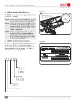
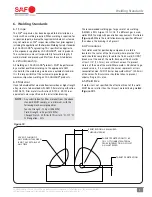
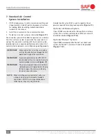
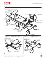
2. Standard Decal Requirements
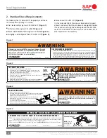
The following five (5) decals MUST be properly installed on
the trailer prior to putting it in service:
Tire Clearance Warning Decal: XL-AR356-01
(Figure 1)
.
Air Release Warning Decal: XL-AR429
(Figure 2)
.
Manual QWIK RELEASE
®
Warning Decal: XL-MS184
(Figure 3)
.
SwingAlign
™
Axle Alignment Decal: XL-AR372-01
(Figure 4)
.
Figure 1
WARNING
Minimum tire clearance
MUST
be maintained between tires and
nearest point of contact on the suspension or vehicle. Premature
tire wear, fire or loss of vehicle control could result from contact
with the tires if clearances are not maintained.
XL-AR356-01
TIRE CLEARANCE REQUIREMENTS
1 INCH (25.4 mm) MINIMUM VERTICAL
feature.
2 INCH (50.8 mm) MINIMUM LATERAL
Axle.
www.safholland.us
Copyright © 2011
#
SAF-HOLLAND, Inc.
Figure 2
WARNING
Failure to properly engage the lock pins could result in loss of vehicle control
which, if not avoided, could result in death, serious injury or property damage.
IMPORTANT: TRAILER EMERGENCY BRAKES MUST BE APPLIED BEFORE MANUAL
AIR RELEASE SWITCH WILL OPERATE.
TO REPOSITION SLIDER:
1. Remove stop bar and move to desired location.
2. Pull manual switch to
“disengaged”
position. (If lock pins do not
retract after manual switch is in
“disengaged”
position, gently rock
trailer and pins will automatically retract.)
3. Carefully move trailer until contacting stop bar.
4. Push manual switch to
“engaged”
position and visually check all lock
pins for proper engagement.
5. Locate stop bar directly behind slider.
6. Before using trailer, the manual air release lock switch must be in
“engaged”
position, and all lock pins must extend through the rails or beams.
AIR RELEASE SWITCH
PUSH TO
“ENGAGE”
LOCK PINS
PULL TO
“DISENGAGE”
LOCK PINS
XL-AR429
www.safholland.us
Copyright © 2012
#
SAF-HOLLAND, Inc.
Figure 3
TO REPOSITION SLIDER:
1. Remove stop bar and move to desired location.
2. Lift pull arm and pull until locked in the
“OUT”
position. (If lock pins do not retract
after pull arm is locked in the
“OUT”
position, gently rock trailer with brakes
applied and pins will automatically retract.)
3. Apply trailer brakes and carefully move trailer until contacting stop bar.
4. Release pull arm to the
“IN”
position and visually check all lock
pins for proper engagement.
5. Locate stop bar directly behind slider.
6. Before moving the trailer, the pull arm must be locked in the
“IN”
position, and all lock pins must extend through the rails or beams.
“IN”
POSITION
“OUT”
POSITION
XB-SL0255
XL-MS184
www.safholland.us
Copyright © 2012
#
SAF-HOLLAND, Inc.
WARNING
Failure to properly engage the lock pins could result in loss of vehicle
control which, if not avoided, could result in death, serious injury or
property damage.
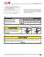
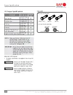
Torque Decal: XL-AR418-01
(Figure 5)
.
It is the responsibility of the end user to periodically inspect
all decals and ensure that they are clean and completely legible.
If any decals are missing, loose, damaged or difficult to read,
contact SAF-HOLLAND
®
Customer Service at 888-396-6501 to
order replacements immediately.
Figure 4
ALIGNMENT BOLT IS ON THE FRONT OF THE ROADSIDE FRAME BRACKET:
XL-AR372-01
STEP 1.
Before aligning axle, pull trailer forward in a straight line for a sufficient distance to insure there are no binds
in the suspension and then lock the brakes so the slider lock pins rest against the rear of the body rail holes.
STEP 2.
Check to verify trailer is empty and emergency brakes are
NOT
engaged.
STEP 3.
Rotate bolt
CLOCKWISE
to move axle forward (A arrows);
COUNTERCLOCKWISE
to move axle rearward (B arrows).
A = axle forward
B = axle rearward
ALIGNMENT BOLT HEAD
NOTE:
1/2 turn of
free play in either
direction (A or B)
is acceptable.
SWINGALIGN
™
NON-WELDED AXLE ALIGNMENT PROCEDURES
www.safholland.us
Copyright © 2011
#
SAF-HOLLAND, Inc.


