10
XL-AS20012BM-en-US Rev B · 2014-05-28 · Amendments and Errors Reserved · © SAF-HOLLAND, Inc., SAF-HOLLAND, HOLLAND,
SAF, and logos are trademarks of SAF-HOLLAND S.A., SAF-HOLLAND GmbH, and SAF-HOLLAND, Inc.
Installation Instructions
8. Slider Assembly Installation
1. Remove the hold down clips on all four (4) corners of
the slider.
2. Locate the slider between the body rails of the trailer and
engage the lock pins. Refer to the slider re-positioning
operating instructions in Section 12 of this manual.
3. Once the slider is correctly positioned, re-install the hold
down clips to the slider and body rails, and torque all
IPMEEPXODMJQOVUTUPGUMCT /tN
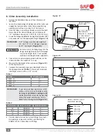
4. Ensure the linkage assembled to the height control valve (HCV)
and suspension is of the appropriate height
(Figure 12)
.
IMPORTANT:
A 15" linkage is used for ride heights of
16", 16.5"-17". A 16" linkage is required
for 18" ride heights
(Figure 16)
.
Failure to match the linkage length to the
design ride height could result in improper
suspension height which, if not avoided,
could result in damage to trailer components.
5. Connect service and emergency gland hand lines to the
slider and allow the suspension to air up.
6. Measure the ride height of the suspension
(Figure 13)
with a tape measure.
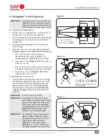
7. Compare the measured suspension ride height value to
the appropriate value
(Table 1)
. Ensure your measured
ride height value is within ± 1/4" (6 mm).
IMPORTANT:
If your measured ride height value is NOT
within ± 1/4"(6 mm); use the table to verify
the linkage length
(Table 2 and Figure 12)
,
and the hole location where the top mounting
stud of the height control valve (HCV) is
bolted to the mounting bracket
(Figure 14)
.
8. Visually check all air control system fittings for air leaks
by applying a soapy water solution and checking for
bubbles at all air connections and fittings.
MODEL
“A” RIDE HEIGHT
CBX69 - 16
16"
CBX69 - 16.5
16.5"
CBX69 - 17
17"
CBX69 - 18
18"
Table 1
RIDE HEIGHT
HOLE LOCATION
LINKAGE LENGTH
16"
2ND HOLE
15"
16.5"
3RD HOLE
15"
17"
4TH HOLE
15"
18"
4TH HOLE
16"
Table 2
Figure 13
Figure 14
Figure 12
HEIGHT CONTROL VALVE
MOUNTING BRACKET
TOP HOLE
2ND HOLE
3RD HOLE
4TH HOLE
LOWER LINKAGE
CONNECTION
HEIGHT CONTROL
VALVE ARM
16", 16.5" AND 17"
RIDE HEIGHTS
REQUIRE 15" LINKAGE
18" RIDE HEIGHT
REQUIRES 16" LINKAGE
“A”
RIDE
HEIGHT


