background image

English 16 English 

Customer Assistance Policy 

The business of The Lincoln Electric Company is 
manufacturing and selling high quality welding equipment, 
consumables, and cutting equipment. Our challenge is to 
meet the needs of our customers and to exceed their 
expectations. On occasion, purchasers may ask Lincoln 
Electric for advice or information about their use of our 
products. We respond to our customers based on the best 
information in our possession at that time. Lincoln Electric 
is not in a position to warrant or guarantee such advice, 
and assumes no liability, with respect to such information 
or advice. We expressly disclaim any warranty of any 
kind, including any warranty of fitness for any customer’s 
particular purpose, with respect to such information or 
advice. As a matter of practical consideration, we also 
cannot assume any responsibility for updating or 
correcting any such information or advice once it has 
been given, nor does the provision of information or 
advice create, expand or alter any warranty with respect 
to the sale of our products 
Lincoln Electric is a responsive manufacturer, but the 
selection and use of specific products sold by Lincoln 
Electric is solely within the control of, and remains the sole 
responsibility of the customer. Many variables beyond the 
control of Lincoln Electric affect the results obtained in 
applying these types of fabrication methods and service 
requirements. 
Subject to Change – This information is accurate to the 
best of our knowledge at the time of printing. Please refer 
to 

www.saf-fro.com

 for any updated information. 


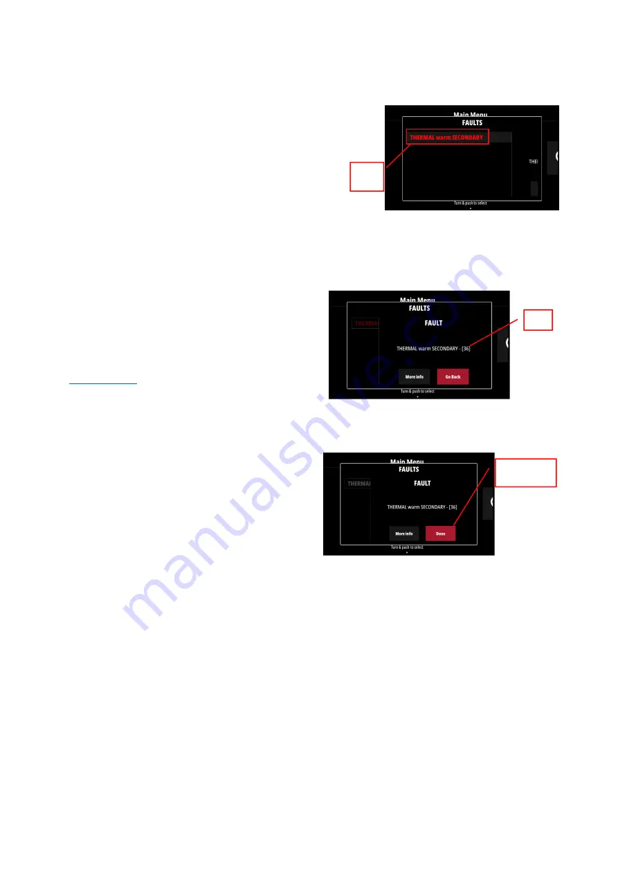
Error Codes and troubleshooting 

When the error occurs and remains, the Error messages 
is displayed in Red. 


By pushing the knob button, the Error code number is 
displayed. 
 
During error, new welding sequence is blocked until the 
reason of error remains. 


When the error vanished, it is now possible to 
acknowledge the error by pushing the knob. The 
background error message becomes white 


Table 1 shows list of basic errors that can appear. To get 
full list of error codes, please contact local service. 


Type of 

error 

Error 
code 

“Done”, starting a
new sequence is
possible 

Summary of Contents for PRESTO 275

Page 1: ...IM3137 02 2022 REV01 PRESTO 275 OPERATOR S MANUAL ENGLISH Lincoln Electric Bester Sp z o o ul Jana III Sobieskiego 19A 58 260 Bielawa Poland ...

Page 2: ... enter your product identification data in the table below Model Name Code Serial Number can be found on the machine rating plate Model Name Code Serial number Date Where Purchased INDEX Technical Specifications 1 ECO design information 2 Electromagnetic Compatibility EMC 4 Safety 5 Introduction 7 Installation and Operator Instructions 7 WEEE 18 Spare Parts 18 REACh 18 Authorized Service Shops Loc...

Page 3: ...period Output Current I2 GTAW 100 200A 60 230A 40 270A SMAW 100 180A 60 230A 25 270A OUTPUT RANGE Welding Current Range Peak Open Circuit Voltage U0 GTAW 5 270A 70V SMAW 5 270A RECOMMENDED INPUT CABLE AND FUSE SIZES Fuse Type gR or Circuit Breaker Type Z Power Lead PRESTO 275 16A 400V AC 4 Conductors 1 5mm2 DIMENSIONS AND WEIGHT Weight Height Width Length PRESTO 275 14 1Kg 360 mm 230 mm 498 mm Pro...

Page 4: ...de X STICK mode After 30 minutes of non working X Fan off X The value of efficiency and consumption in idle state have been measured by method and conditions defined in the product standard EN 60974 1 20XX Manufacturer s name product name code number product number serial number and date of production can be read from rating plate XXXXXXXXXX Code XXXXX XXXXXX X S N P1YYMMXXXXX 1 2 3 4 5 P1 YY MM X...

Page 5: ... process gas usage depends on cross sectional area of the nozzle For commonly used torches Helium 14 24 l min Argon 7 16 l min Notice Excessive flow rates causes turbulence in the gas stream which may aspirate atmospheric contamination into the welding pool Notice A cross wind or draft moving can disrupt the shielding gas coverage in the interest of saving of protective gas use screen to block air...

Page 6: ...r adjacent to the work area and the machine Radio and or television transmitters and receivers Computers or computer controlled equipment Safety and control equipment for industrial processes Equipment for calibration and measurement Personal medical devices like pacemakers and hearing aids Check the electromagnetic immunity for equipment operating in or near the work area The operator must be sur...

Page 7: ...ccordance with local electrical regulations ELECTRICALLY POWERED EQUIPMENT Regularly inspect the input electrode and work clamp cables If any insulation damage exists replace the cable immediately Do not place the electrode holder directly on the welding table or any other surface in contact with the work clamp to avoid the risk of accidental arc ignition ELECTROMAGNETIC FIELD MAY BE DANGEROUS Ele...

Page 8: ...ielding gas for the process used and properly operating regulators designed for the gas and pressure used Always keep cylinders in an upright position securely chained to a fixed support Do not move or transport gas cylinders with the protection cap removed Do not allow the electrode electrode holder work clamp or any other electrically live part to touch a gas cylinder Gas cylinders must be locat...

Page 9: ...C Duty cycle and Overheating The duty cycle of a welding machine is the percentage of time in a 10 minute cycle at which the welder can operate the machine at rated welding current Example 60 duty cycle Welding for 6 minutes Break for 4 minutes Excessive extension of the duty cycle will cause the thermal protection circuit to activate Minutes or decrease Duty Cycle Input Supply Connection WARNING ...

Page 10: ...or Back panel PRESTO 275 Figure 2 1 Power switch User Interface Figure 3 1 Display 5 TFT display shows welding processes parameters 2 Left button Home Back 3 Central Knob Parameter access and validation by pushing knob 4 Right Button Access to specific parameter of the current selected page Main Menu Figure 4 In Main Menu 3 selections are possible GTAW allow to enter in TIG Home Menu SMAW allow to...

Page 11: ...rameters 6 Contextual Buttons Encoders Labels informs the user of features associated to the knob and buttons Welding GTAW process To select TIG mode process select the GTAW icon and push the knob button Only Touch start Home menu Figure 6 1 Main Menu access push this button to go back 2 Push button to configure all parameters of current process Turn the knob to adjust the welding current value 3 ...

Page 12: ...he knob button Home menu Figure 11 1 Main Menu access push this button to go back to Main Menu 2 Push button to configure all parameter of current process Turn the knob to adjust the welding current value 3 Memories access See dedicated section 4 Secondary settings User can see directly on Home page the current parameter values Configure Parameters Stick modes Figure 12 To change the Stick modes s...

Page 13: ...ith 40 of welding current added Example if welding current is 100A the Hot Start current will be 40 Arc Force This is a temporary increase in the output current during normal stick welding This temporary increase in output current is used to clear intermittent connections between the electrode and the weld puddle that occur during normal stick welding Figure 15 Anti Sticking This feature cannot be...

Page 14: ...respond to the position of the remote control potentiometer from minimum to maximum current Minimum and maximum can be defined in the Remote Range In above example the minimum current is 25A and the maximum is 250A Foot Pedal Usable in GTAW only When selected the maximum current is the one set on Home page by the knob The minimum current is like Hand Remote the one set on Remote Range section As m...

Page 15: ...fore the end of saving process slot will not be erased Guided Setup Guide Setup is a feature for SMAW which configures automatically the power source according to a set of input data Type of metal sheet Type of electrode Electrode diameter Based on this data the power source will be automatically configured to get the most suitable parameter for the configuration Guide Setup activation Guided Setu...

Page 16: ...es Export from power source to memories previously saved USB Key Load Only Memories Import from USB key to power source memories previously saved USB Key Enable Data Monitoring on USB key Activation of Data Monitoring is possible only when USB key is plugged A csv file is created on USB where average voltage average current arc time and process selected Data monitoring remains active even if USB k...

Page 17: ...commended to contact the nearest Technical Service Center or Lincoln Electric Repairs and modifications performed by unauthorized service or personnel will cause that the manufacturer s warranty will be lost Any noticeable damage should be reported immediately and repaired Routine maintenance everyday Check condition of insulation and connections of the work leads and insulation of power lead If a...

Page 18: ...ation or advice create expand or alter any warranty with respect to the sale of our products Lincoln Electric is a responsive manufacturer but the selection and use of specific products sold by Lincoln Electric is solely within the control of and remains the sole responsibility of the customer Many variables beyond the control of Lincoln Electric affect the results obtained in applying these types...

Page 19: ... operation by the torch trigger 37 The machine has shut down because it has overheated System detected a temperature level beyond the normal system operating limit Be sure process does not exceed duty cycle limit of the machine Check the setup for proper air flow around and through the system Check that the system has been properly maintained including removal of accumulated dust and dirt from the...

Page 20: ...n this printing First read the Part List reading instructions above then refer to the Spare Part manual supplied with the machine that contains a picture descriptive part number cross reference REACh 11 19 Communication in accordance with Article 33 1 of Regulation EC No 1907 2006 REACh Some parts inside this product contain Bisphénol A BPA EC 201 245 8 CAS 80 05 7 Cadmium EC 231 152 8 CAS 7440 43...

Page 21: ... 50C50 W000260682 REMOTES CONTROL Manual remote control K10095 1 15M Foot remote control K870 OPTIONS Cart 24 K14191 1 Cart 24 interface to order with Cart 24 K14384 1 Cover K14383 1 Extension Cord 15m K14148 1 Warning Increasing the length of torch or return cables more than manufacturer maximum specified length will increase the risk of electric shock Only 2 Extension Cord for a maximum total le...

Reviews: