3.4
De s c ri pt i on of c a b l e c onne
c t i on
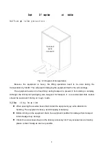
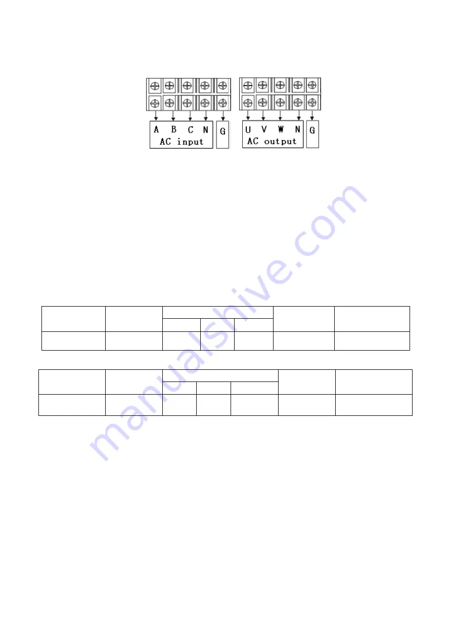
The cable connection of the main circuit is as shown:
Fig. 3-3 Schematic diagram of wiring terminal
Before installing the equipment, all the switches are to be disconnected. The circuit cables
should be connected properly according to the above diagram.
3.5
C a b l e w i ri ng
1)
Use a voltmeter to confirm that there is no voltage output in the distribution lines;
2)
Confirm that all of the switches of the variable frequency power supply are in the “OFF”
position;
3)
The input and output cables can be selected according to the cables recommended by Saelig.
Model AFV-33030U is shown as an example in Tables 3-1 and 3-2.
Table 3-1 Reference table of input distribution cables
Machine model
Input current
(A)
Input live wire
(mm
2
)
Input zero line
(mm
2
)
Input ground wire
(mm
2
)
A
B
C
AFV-33030U
70.8A
25mm
2
25mm
2
25mm
2
16mm
2
16mm
2
Table 3-2 Reference table of output distribution cables
Machine model
Output
current
(A)
Output live wire
(mm
2
)
Output zero
line
(mm
2
)
Output ground wire
(mm
2
)
U
V
W
AFV-33030U
LO
:
83.3A
HI
:
41.7A
25mm
2
25mm
2
25mm
2
25mm
2
16mm
2
The reference cables recommended in the above-mentioned tables are multi-core flexible copper
cables. The user can select different cables according to the input and output current conditions.
When the length of the input or output lines exceed 20 meters, it is recommended that the wire
diameter of the cable should be doubled.
4)
Properly connect the input distribution lines to the corresponding wiring terminals at the input
terminal of the equipment, and connect the output load lines to the corresponding wiring
terminals at the output terminal of the equipment.
Note: The c orresponding relationship during wiring is generally A, B and C
correspond to the common yellow, green and red; the N wire must be connected
properly; DO NOT operate a charged device; when the input and output wiring distance
is long, it should be considered that the line voltage drops in the wires.
6


