background image

10

Sabine Smart Spectrum

®

 Wireless

© 2011  Sabine

, Inc.

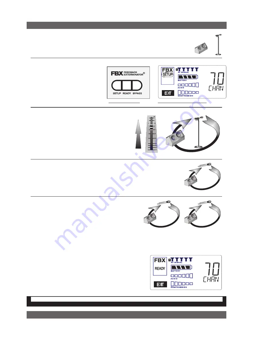
Fig. 3d - FBX: SETUP

Fig. 3e - SETUP indicator flashing

Quick Setups

3.2.  FBX Quick Setup


Place microphone and speakers in primary position.

1
2


Press and hold the 

SETUP button

 (Fig. 

3d) on the receiver until the LCD 

SETUP 

indicator

 (Fig. 3e) flashes 4 times and 

SETUP stays lit — then release it. 


NOTE: DO NOT TALk INTO yOUR SySTEM while in 
Setup Mode.


Slowly raise the gain on the mixer

 or amp until FBX 

eliminates the first few feedback tones. With each new 
feedback frequency, you will hear a short, quiet burst of 
feedback that will disappear immediately as a filter is 
set.


Pause raising the gain, and move the microphone to another area where it will be used.  
Resume slowly raising the mixer gain, until FBX eliminates a few more feedback tones.


NOTE: When choosing microphone setup locations, try to anticipate likely areas where 
the microphone will be positioned or moved to, or areas that may be especially prone to 
feedback problems (e.g., under an overhead speaker).

Location #1

Location #2

Location #3


Repeat until the 

SETUP 

indicator automatically turns off and 

the 

READy 

indicator comes on. 


NOTE:

 You may quit 

SETUP 

mode at any time prior to its auto-

matic exit by simply pressing the 

READy 

button. This will enable 

ready-to-operate status, but with fewer fixed FBX filters in place.  
In the default factory setting, dynamic FBX filters will still be held 
in reserve to catch and eliminate new feedback, regardless of 
how or when SETUP mode is exited. (See 

Section 14.3.2 

for 

details on the differences between fixed and dynamic FBX filters 
and 

Section 13.4.2.1

 for instructions on changing the balance 

5

4

3

FBX BYPASS CAuTIon

Bypassing FBX filters may allow suppressed feedback to be released!

Location #4

(if necessary)

Mixer Channel

of fixed versus dynamic FBX filters using the Remote Control Software or 

Appendix D

 for using the Dip Switches on 

the back of the receiver).

3.2.2. FBX Bypass

The 

ByPASS button

 (Fig. 3d) bypasses only the FBX filters, and not 

the additional signal processing (de-essing, compression and Mic 
SuperModeling

TM

) available on the True Mobility

TM

 Wireless Receiver. 

This is a useful button that allows comparison of the sound quality 
when FBX filters are in place, to the sound with no filters (the qual-
ity should be very similar).  

Before pressing ByPASS, take care 

to reduce your overall system gain so that you do not release 
suppressed feedback!

Summary of Contents for SWM7000 -

Page 1: ...Operating Guide SWM6000 915 MHz Systems SWM7000 2 4 GHz Systems WIRELESS MICROPHONES the sound of innovation W I R E L E S S SYS T E M S...

Page 2: ......

Page 3: ...with Council Directive 73 23 EEC and 89 336 EEC EMC Directives Standards to which conformity is declared EN 60065 2001 EN 55022 1998 Class B EN 50082 1 1998 Transmitters SABINE MODEL SW70 H and SW75 T...

Page 4: ...55 Appendix C Specifications 56 Appendix D Dip Switch Settings 58 Appendix E Frequency Chart 59 Appendix F Battery Endurance Tests Typical 60 Appendix G Changing Audix Mic Capsules SW70 H 60 16 CAUTI...

Page 5: ...a Sabine Extension Antennas Antenna Distribution Amplifier also available for multi receiver installations Section 13 Sabine Remote Control Software how to control up to 70 channels from one PC Sectio...

Page 6: ...Level RF Ch Select Compressor Limiter De esser Mic Model FBX Fig 2e SW71 R SW61 R One channel Receiver Fig 2d SW72 R SW62 R Two channel Receiver Fig 2c SW72 NDR SW62 NDR Two channel Receiver w Network...

Page 7: ...ent VT Antennas SWA700 TNC Front to Rear Converter Kit Set of 2 SWA6SS Antenna Distribution Amp for 6 systems SWASS EXT Extension Antenna Kit Set of 2 SWAANT Dipole Antennas 2 SWATNC N RF Adaptor cabl...

Page 8: ...ll transmitters are off Position receiver so that the antennas are within visual range of the intended transmitter locations Transmitter range is about 100 meters but structural objects in the transmi...

Page 9: ...djust the receiver Output Level to supply a strong input level to the mixer amplifier or active loud speaker If your receiver output is connected to a microphone level input on the mixer keep the rece...

Page 10: ...the READY indicator comes on NOTE You may quit SETUP mode at any time prior to its auto matic exit by simply pressing the READY button This will enable ready to operate status but with fewer fixed FBX...

Page 11: ...ercussive attack of the guitar notes In general be wary of too much gain makeup and too high a compression ratio which may make a noisy guitar amplifier more objectionable Ratio settings might range f...

Page 12: ...ver and light sources such as fluo rescent bulbs or neon signs which may emit very short range broadband interference Maximize the distance between transmitters and receivers and potential sources of...

Page 13: ...chnology See caution at left Wireless Video Cameras Certain wireless video cameras X10 for example use the 2 4 GHz band These devices are also very low power and in general should not present a proble...

Page 14: ...nas 4 2 Displays and Settings Your Sabine Smart Spectrum handheld microphone and belt pack transmit ter have many powerful features all of which are easily monitored using the transmitter LCD display...

Page 15: ...irect plug in or by placing the handheld mic in the Sabine charging clip BATTERYVOLTAGE LEVEL METER Indicates measured battery voltage the more segments illuminated the higher the voltage and the grea...

Page 16: ...unwanted low frequency content Pressing the Up or Down button toggles between the conditions of no filter indicated in the display as L 0 or low roll off indicated by L 75 INTERNAL CONTROL OF EXTERNAL...

Page 17: ...il more quickly in subsequent uses This problem is usually referred to as battery memory Fortunately Sabine s innovative Tireless Wireless Charger takes steps to avoid this problem by automatically re...

Page 18: ...hen a battery is fully charged and turns off the charging cycle 5 The Tireless Wireless Charger prevents futile attempts to resus citate dead batteries if the battery is unresponsive the charging cycl...

Page 19: ...type of battery and will not begin charging Again the battery indicator on the transmitter will flash the right side element indicating testing no charging see Fig 4h Battery Warnings When the transm...

Page 20: ...our wireless channel including battery status information sent from the transmitter by telemetry The right two thirds of the display primarily shows status information regarding the condition of your...

Page 21: ...ting SETUP has been performed and FBX filters are active BYPASS indicates the audio signal is NOT going through FBX filters but all other DSP processing is active Front Panel Lock Status LOCK 1 indica...

Page 22: ...9 1 about the middle of the range the RPI will display about one half of the bar NOTE The setting range of each control is printed on the front panel below each knob 5 2 2 Channel Select Contrast Butt...

Page 23: ...el device turn up the receiver output For best results follow the golden rule of gain structure maximize gain at early stages in the signal path to minimize noise that will be accumulated and amplifie...

Page 24: ...ntil your instrument sounds like it does when patched direct The Cord Simulator replaces the De Esser function only when a beltpack trans mitter is turned on and set to GUI mode 5 7 Receiver Antenna P...

Page 25: ...ems that may affect the other one 6 When using multiple receivers try to maintain at least 1 foot 30 cm distance between antennas from different units If you are rack mount ing multiple receivers you...

Page 26: ...are designed for use with either of Sabine s dynamic handheld microphone transmitters SW60 or 70 H13 and H15 The remaining three Shure Beta 87A AKG C535EB and Audio Technica ATM 89R are designed for u...

Page 27: ...from Sabine and follow the dialog box instructions 3 The last dialog box will allow you to either connect to a re ceiver and update the mic models on that receiver or cancel and complete the upgrade...

Page 28: ...d gain level In that case in the factory default condition you will reserve three unset Dynamic filters for standby 7 1 4 FBX Filter Width Sabine s experience and testing with filters and sound qualit...

Page 29: ...9 Slowly raise the mixer channel gain to the point of feedback and then slowly beyond until you hear the chirping tones of feedback quickly being eliminated by FBX filters setting Stop raising gain af...

Page 30: ...ression ratio is high enough to qualify as a limiter 2 Perceived increase in loudness Because compressed peak levels are kept from rising as high as uncompressed signals you gain headroom for your aud...

Page 31: ...lly work well for voice However too strong a compression ratio too low a threshold and too fast an attack may attenuate speech consonants which provide important intelligibility cues to the audience t...

Page 32: ...of a performer s message and command of the audience don t remove dynam ics just control them This may be particularly true for percussive musical instruments such as drums 8 5 Release Knee Settings T...

Page 33: ...cur with other types and patterns of microphones The range of frequencies affected by sibilance starts above 2 KHz and generally tapers off above 10 KHz in other words sibilance is primarily a problem...

Page 34: ...y to confirm this action as the LCD Display continues to show the number 01 10 of the preset see Fig 10c After four seconds the LCD Display will revert to an indication of the RF channel 10 2 Loading...

Page 35: ...ies helps manage such potential complexity with four strategies and or system accessories 1 First the dual channel receivers SW72 and SW62 receivers offer a 50 space saving advantage with 2 channel re...

Page 36: ...true diversity reception to each receiver For best results the Antenna Distribution Amplifier should be positioned close enough to the receivers to minimize cable runs In most applications you can use...

Page 37: ...Antenna Cabling Impedence must be 50 Ohm IMPORTANT Active Electronics Antenna Sabine wireless receivers provide antennas with active electronics The inputs to the receiver antenna dis tributor amplif...

Page 38: ...8 AU 9311 Foam Polyethylene 20 Stranded 11 10 4 7 20 47 TNC RG212 U 9861 Polyethylene 15 5 solid 6 11 3 0 36 73 N Silver Plated RG8 U 9913 Semi solid Polyethylene 10 Solid 2 50 1 3 88 170 N RG142 8324...

Page 39: ...m You may use either antenna on the left or right side of your performance space When you mount the extension antennas on a stand or on a wall make sure the short end of the triangle is up 7 In order...

Page 40: ...rols and displays are duplicated in the software In addition a deeper level of software control over receiver operation is enabled These new controls are complete and independent for each transmission...

Page 41: ...ission channel chosen the transmitter pad and low cut filter settings and a warning indication in the case of low RF signal strength For handheld transmitters the software display also shows the type...

Page 42: ...and 16 bit color as defaults for monitor display Windows XP users select 96 dpi screen settings USB or Serial COMM Port 13 2 2 Connections There are three types of connections that are used in a remo...

Page 43: ...completely programmable and may be saved and downloaded to a connected receiver at a later time Display settings e g level compression transmitter settings which are dependent on the presence of actua...

Page 44: ...per left menu bar or use F2 and F3 to immediately change from one to the other To select a channel to edit in either view left click on a channel in All Channel View indicated by a red border around t...

Page 45: ...ry to prevent the possibility of triggering a false filter or to more quickly set the FBX filters There is a trade off between speed of filter placement and how carefully the filter is placed More dem...

Page 46: ...level from an earlier scan and a small yellow T indicates the peak RF level observed over the entire time Left click on any line or channel number brings up the RF Scan data history window allowing yo...

Page 47: ...ns Menu choose Copy Parameters You will see your selected chan nel displayed in a red field labeled Copy Parameters From Select the channels you want to copy to from the Available Channels list then c...

Page 48: ...F interference high voltage equipment lighting equipment etc Check distance between transmitters and receiver antennas Problem Transmitter is off but noise still coming from receiver Solution Check fo...

Page 49: ...n Both of these facts mean such uses of the RF spectrum are less likely to cause interference with or suffer from interference from the use of Sabine s systems 14 3 1 RF Sources Your first step in che...

Page 50: ...lems for your Sabine wireless This is especially true if the telephone uses spread spectrum technology See caution below 4 Wireless Video Cameras Certain wireless video cameras X10 for example use the...

Page 51: ...was the 31 band graphic EQ However an FBX filter offers three distinct advan tages over graphic filters 1 First and most obvious is the automatic nature of FBX filters When feedback occurs FBX respon...

Page 52: ...rice as para metric filters are not nearly as intuitive or simple to use as graphic equalizers Nothing however is easier to use than an FBX filter which enjoys the precision of a parametric filter yet...

Page 53: ...ed to anywhere a wireless microphone might be taken 14 3 2 FBX Fixed Dynamic Filters FBX filters come in two flavors fixed and dynamic Both operate automatically There is no audible difference between...

Page 54: ...y set feedback is still a problem FBX filters may be set to 20 one fifth octave width This wider filter setting will help to better eliminate feedback trouble areas but may also affect music programs...

Page 55: ...SWA6SS Antenna Distribution Amplifiers SWM Series Receivers up to 35 receivers NOTE Connect receiver Antenna 1 input to any RF Output 1 connector on the SWA6SS Likewise connect any receiver Antenna 2...

Page 56: ...Rechargeable or two 1 5V Alkaline AA cells Rechargeable Battery Life 10 hours per charge 500 charge cycles typical Alkaline Battery Life 12 hours typical Digital Signal Processing FBX Filters Ten inde...

Page 57: ...attery Sabine Rechargeable or two 1 5V Alkaline AA cells Rechargeable Battery Life 10 hours per charge 500 charge cycles typical Alkaline Battery Life 12 hours typical Digital Signal Processing FBX Fi...

Page 58: ...ver if the 1 dip switch is not in the down position NOTE 1 LOCK 1 overrides LOCK 2 NOTE 2 Down is the default position NOTE 3 Lock settings are saved with the Presets Networking The first receiver con...

Page 59: ...155102 11 2412 742041 12 2413 535510 13 2415 122449 14 2415 915918 15 2417 502857 16 2418 296327 17 2419 883265 18 2420 676735 19 2422 263673 20 2423 057143 21 2424 644082 22 2425 437551 23 2427 02449...

Page 60: ...3 seconds then let go One of the screens at right will appear in the transmitter LCD showing the currently assigned capsule Using the transmitter control up down buttons select the capsule you now ha...

Page 61: ...in the Radio Interference Regula tions of the Canadian Department of Communications Le present appareil numerique n emet pas de bruits radioelectriques depassant les limites applicables aux appareils...

Page 62: ...nection with any condition that may require dissemination of information or correction 3 You may contact Sabine directly by telephoning 386 418 2000 4 Please have the Sabine product name and serial nu...

Page 63: ...ory 51 53 54 Filter Time Out FBX 45 Front Panel Lock 21 41 45 58 G Gain Compressor 31 Guitar Cord Simulator 24 Guitar Settings 11 H Handheld Mic 14 Headworn Mic 14 High Cut Filters 40 Hot Keys Softwar...

Page 64: ...Sabine Inc 13301 NW US Highway 441 Alachua Florida 32615 8544 USA Phone 386 418 2000 Fax 386 418 2001 www Sabine com WIR E LESS SYSTE MS...

Reviews: