background image

MACHINE OPERATION 

86037580  GLIDE  01/03/07 

       3-16 

 
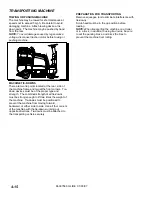
EMPTYING AND CLEANING TANKS 
RECOVERY TANK 

1. 

Touch the one-touch switch (#1) on the control 
panel to raise the scrub deck, stop the motors, 
and solution flow, raise the squeegee and turn 
off vacuum motors. 

2. 

Park the machine next to a floor drain.  Drain 
hose is on left rear corner of machine. 

3. 

Turn off the key switch and set the machine’s 
parking brake. 

4. 

Unhook the drain hose from retainer.  Unscrew 
T-handle on plug enough to loosen plug and 
lower hose in direction of drain.  Stand behind 
end of hose.  Recovered solution will come out 
with force.  Slowly remove plug from drain hose. 

5. 

Remove recovery tank dome.   

6. 

Flush the recovery tank out with clean water. 
Repeat until clean water comes out of drain 
hose.  Do not use water hotter than 140

'

  (60

'

C) 

to clean the tank.  Damage to tank may occur. 

7. 

Replace plug and secure drain hose in bracket. 

8. 

If machine is to be stored, leave recovery tank 
dome open and drain hose plug off. 


SOLUTION TANK 

1. 

Park the machine next to a floor drain.  Drain 
hose is on left rear adjacent to recovery tank 
drain hose.


2. 

Turn off the key switch and set the machine’s 
parking brake.


3. 

Unhook the small drain hose from the retainer. 
Lower hose in direction of the drain.  


4. 

Remove the solution tank cover.


5. 

Flush the solution tank out with clean water and 
run several gallons of clean water through 
systems.  Do not use water hotter than 140º F 
(60º C) to clean tank.  Damage may occur.


NOTE: Never allow solution to remain in tank.  
Damage to tank, seals and valves could occur. 

6. 

Secure drain hose in bracket. 


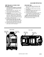
REAR VIEW 

TOP VIEW 

RECOVERY 
DRAIN HOSE 

SOLUTION 
DRAIN HOSE

RECOVERY 
TANK DOME 

SOLUTION 
TANK COVER

Summary of Contents for Glide SG28

Page 1: ...8 SG32 SG36 SGW32 1 005 245 0 1 005 246 0 1 005 247 0 1 005 307 0 AFTER SN 1000136404 86037580 04 06 20 PRV NO 980207 SCRUBBER IPX4 Operating Instructions ENG Read these instructions before using the...

Page 2: ...____________ SALES REPRESENTATIVE _____________________ DEALER NAME ________________________________ OPERATIONS GUIDE NUMBER ___________________ PUBLISHED __________________________________________ OV...

Page 3: ...Batteries 4 2 Battery Maintenance 4 2 Checking Battery Specific Gravity 4 2 Charging the Batteries 4 3 Changing Batteries 4 4 Battery Connections 4 4 Battery Tray Drain Hose 4 4 Squeegee 4 5 Adjusting...

Page 4: ...tion contains assembled parts illustrations and corresponding parts list The parts lists include a number of columns of information REF column refers to the reference number on the parts illustration...

Page 5: ...ercial use for example in hotels schools hospitals factories shops and offices for more than normal housekeeping purposes Maintenance and repairs must be done by qualified personnel If foam or liquid...

Page 6: ...information carefully Know when these conditions can exist Locate all safety devices on the machine Please take the necessary steps to train the machine operating personnel FOR SAFETY DO NOT OPERATE...

Page 7: ...he labels become illegible promptly replace them SAFETY DECAL 86252530 PRV NO 81494 BATTERY CAUTION 86252520 PRV NO 80885 HORN DECAL 86248210 PRV NO 81349 CIRCUIT BREAKER 86244130 28 IN 32 IN PRV NO 5...

Page 8: ...lution tank capacity 30 gal 115 L Recovery tank capacity 30 gal 115 L Scrub brush diameter for 28 in 71 cm disk scrub head 14 inch 35 5 cm Scrub brush diameter for 32 in 81 cm disk scrub head 16 inch...

Page 9: ...ot mean square acceleration at the operator s arms was measured to be below 2 5m s2 This was a tri axial third octave band measurement made during normal operation on a composite tile floor The measur...

Page 10: ...the down pressure on the scrub deck The 36 in disk scrub system consists of three rotary type disk scrub brushes motors scrub deck skirts lift actuator shift actuator and controls The brushes scrub th...

Page 11: ...2 Front cover 3 Side cover 4 Tank 5 Recovery tank cover 6 Recovery tank dome 7 Recovery tank drain hose 1 2 4 3 11 5 6 8 9 10 12 13 7 8 Scrub head 9 Scrub head side squeegee 10 Solution tank drain ho...

Page 12: ...CONTROLS 86037580 GLIDE 01 03 07 3 5 1 2 3 4 5 6 7 11 14 15 12 21 17 13 20 18 20 19 16 21 10 9 8...

Page 13: ...19 Squeegee camber adjustment knob 20 Squeegee deflection adjustment knob 21 Side squeegee deflection adjustment knob 1 KEY SWITCH Controls the power for the machine functions To turn the machine pow...

Page 14: ...ill rise and the brush pressure indicator will display error code 9000 To stop scrubbing press the one touch switch The brush drive motors will turn off the scrub deck will raise the solution flow wil...

Page 15: ...djust the solution flow to the scrub deck without resetting each time the scrubbing operation is interrupted If recycling option is installed this switch controls the amount of solution flow to the sc...

Page 16: ...spent with the brushes running and gives true brush motor time Brush Run Time Key ON Hours Traction Motor Time Fault codes icon will appear on either display screen when the controller detects a prob...

Page 17: ...orizontal bars in the battery meter box When the batteries require charging the icon will flash and a battery inhibit icon will appear on the right side of either information screen Scrub and solution...

Page 18: ...e is an adequate amount of water in recovery tank before starting recycle pump and turn off recycle pump when water level reaches filter To stop the solution recycle pump press the switch The pump wil...

Page 19: ...or servicing machine stop on level surface set parking brake turn off machine and remove key 14 DIRECTIONAL CONTROL PEDAL AND SPEED REDUCTION FEATURE This pedal controls the direction of travel and th...

Page 20: ...n front of seat at the bottom While in a standing position grasp the back of the seat and the seat adjustment grab bar and lift seat into the adjustment slot and lower into one of the locking position...

Page 21: ...rn off machine and remove key 1 Set squeegee and scrub deck to up position set parking brake and turn off key switch 2 Remove solution tank cover Flammable materials can cause an explosion or fire Do...

Page 22: ...lear the vacuum hose of recovered solution 2 Allow directional pedal to return to neutral 3 Apply brake to stop machine 4 Turn key switch off 5 Set parking brake FOR SAFETY Before leaving or servicing...

Page 23: ...es out of drain hose Do not use water hotter than 140 60 C to clean the tank Damage to tank may occur 7 Replace plug and secure drain hose in bracket 8 If machine is to be stored leave recovery tank d...

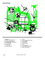
Page 24: ...t 4 Side Squeegee Adjustment 5 Scrub Brushes 6 Vacuum Filter 7 Float Switch 8 Solution Strainer 14 6 7 8 15 2 9 12 10 5 4 13 9 Brake 10 Steering Chain Tensioner 11 Vacuum Motor 12 Brush Motor 13 Tract...

Page 25: ...t overfill Keep plugs firmly in place at all times When servicing machine avoid contact with acid Batteries emit hydrogen gas Explosion or fire can result Keep sparks and open flame away Keep covers o...

Page 26: ...erflow resulting in loss of battery acid balance and damage to the machine 5 Replace battery caps and leave them in place while charging 6 Unplug the battery connector from the machine Unplug the batt...

Page 27: ...one at a time 9 Prepare a suitable battery site to place batteries 10 Attach suitable battery lifting device and lift batteries from the machine Batteries are a potential environmental hazard Consult...

Page 28: ...rease the deflection of the squeegee blade at the ends turn knob on squeegee trailing arm clockwise To increase the deflection at the ends of the squeegee assembly turn knob counter clockwise 5 Again...

Page 29: ...tion turn off the key switch and set the parking brake FOR SAFETY Before leaving or servicing machine stop on level surface turn off machine and remove key 2 Disconnect vacuum hose and loosen the two...

Page 30: ...lade 3 Remove the retaining strap and squeegee blade and rotate or replace the blade 4 Install blade and retaining strap on locating pin and reinstall three nuts and bolts 5 Tighten nuts Do not over t...

Page 31: ...re used for easy and complete removal of old floor waxes finishes They will quickly remove ground in dirt black heel marks and spills When used with the proper stripper this pad leaves the floor clean...

Page 32: ...lve from debris If there is little or no solution flow to the ground check the strainer for debris Drain the solution tank and clean the solution strainer To remove the strainer turn the bottom part o...

Page 33: ...d extremely pitted or not concentric the motor will need to be replaced or sent to a qualified service center Important These brushes wear quicker as the length shortens due to increased heat Spring i...

Page 34: ...n motor barrel to motor cap and motor barrel to motor frame 2 Remove end cap from motor NOTE Motors contain two wave washers in cap Do not lose these 3 Release brush from spring tension Remove screw c...

Page 35: ...osition held into brush holder by spring tension 9 Carefully place end cap onto bearing on motor shaft NOTE On motors use care to assure wave washer alignment 10 With cap end in partially installed po...

Page 36: ...xle in the lowered extended position To adjust the actuator 1 While holding actuator barrel to prevent it from spinning apply power to the actuator such that it is fully extended Positive power to whi...

Page 37: ...stops barely touch the rubber bumpers on the frame in the raised retracted position To adjust the actuator 1 While holding actuator barrel to prevent it from spinning apply power to the actuator such...

Page 38: ...st be of the proper type and strength The combined strength of all tie downs must be strong enough to lift two times the weight of the machine Tie downs must be positioned to prevent the machine from...

Page 39: ...raised use jack stands at the designated jack locations Support the front of the machine by placing jack stands or solid wood blocks under the U shaped stabilizer bars FOR SAFETY Block machine at des...

Page 40: ...motors to dry Clean brushes or pads and check wear Clean main and side squeegee blades and check wear Clean out recovery tank and vacuum filter Clean and inspect float shutoff Clean outside of tanks...

Page 41: ...ake switch connection or faulty brake switch Check connections and switch continuity Little or no propel Loose seat switch connection or faulty seat switch Check connections and switch continuity Faul...

Page 42: ...tion tank empty Fill solution tank Solution flow turned off or set too low Turn on or increase flow setting Solution strainer plugged Clean solution strainer Solution system plumbing obstructed Clear...

Page 43: ...communications timeout Wiring fault on 6 way serial link between controller and display 7501 LCD module settings corrupt Disconnect batteries and wait 1 minute before re applying power All 760_ Codes...

Reviews: