


G
General notes
Our “General Terms and Conditions for Business“ together with the “General Conditions for the Supply of Products and Services of the Electrical
and Electronics Industry“ (ZVEI conditions) including supplementary clause “Extended Retention of Title“ apply as the exclusive terms and conditions.
In additionIn addition, the following points are to be observed:
– These instructions must be read before installation and putting in operation and all notes provided therein are to be regarded!
– Devices must only be connected to safety extra-low voltage and under dead-voltage condition. To avoid damages and errors the device
(e.g. by voltage induction) shielded cables are to be used, laying parallel with current-carrying lines is to be avoided, and EMC directives are to
be observed.
– This device shall only be used for its intended purpose. Respective safety regulations issued by the VDE, the states, their control authorities,
the TÜV and the local energy supply company must be observed. The purchaser has to adhere to the building and safety regulations and has to
prevent perils of any kind.
– No warranties or liabilities will be assumed for defects and damages arising from improper use of this device.
– Consequential damages caused by a fault in this device are excluded from warranty or liability.
– These devices must be installed by authorised specialists only.
– The technical data and connecting conditions of the mounting and operating instructions delivered together with the device are exclusively
valid. Deviations from the catalogue representation are not explicitly mentioned and are possible in terms of technical progress and continuous
improvement of our products.
– In case of any modifications made by the user, all warranty claims are forfeited.
– This device must not be installed close to heat sources (e.g. radiators) or be exposed to their heat flow. Direct sun irradiation or heat
irradiation by similar sources (powerful lamps, halogen spotlights) must absolutely be avoided.
– Operating this device close to other devices that do not comply with EMC directives may influence functionality.
– This device must not be used for monitoring applications, which serve the purpose of protecting persons against hazards or injury,
or as an EMERGENCY STOP switch for systems or machinery, or for any other similar safety-relevant purposes.
– Dimensions of enclosures or enclosure accessories may show slight tolerances on the specifications provided in these instructions.
– Modifications of these records are not permitted.
– In case of a complaint, only complete devices returned in original packing will be accepted.
These instructions must be read before installation and putting in operation and all notes provided therein are to be regarded!
Devices are to be connected under dead-voltage condition. Devices
must only be connected to safety extra-low voltage. Consequential
damages caused by a fault in this device are excluded from warranty
or liability. Installation of these devices must only be realized by au-
thorized qualified personnel. The technical data and connecting con-
ditions shown on the device labels and in the mounting and operating
instructions delivered together with the device are exclusively valid.
Deviations from the catalogue representation are not explicitly men-
tioned and are possible in terms of technical progress and continu-
ous improvement of our products. In case of any modifications made
by the user, all warranty claims are forfeited. Operating this device
close to other devices that do not comply with EMC directives may
influence functionality. This device must not be used for monitoring
applications, which solely serve the purpose of protecting persons
against hazards or injury, or as an EMERGENCY STOP switch for sys-
tems or machinery, or for any other similar safety-relevant purposes.
Dimensions of enclosures or enclosure accessories may show slight
tolerances on the specifications provided in these instructions.
Modifications of these records are not permitted.
In case of a complaint, only complete devices returned in original
packing will be accepted.
Notes regarding mechanical mounting and attachment:
Mounting shall take place while observing all relevant regulations
and standards applicable for the place of measurement (e.g. such as
welding instructions, etc.). Particularly the following shall be regarded:
– VDE ⁄ VDI directive technical temperature measurements,
measurement set - up for temperature measurements.
– The EMC directives must be adhered to.
– It is imperative to avoid parallel laying of current-carrying lines.
– We recommend to use shielded cables with the shielding being
attached at one side to the DDC ⁄ PLC.
Before mounting, make sure that the existing thermometer‘s techni-
cal parameters comply with the actual conditions at the place of
utilization, in particular in respect of:
– Measuring range
– Permissible maximum pressure, flow velocity
– Installation length, tube dimensions
– Oscillations, vibrations, shocks are to be avoided (< 0.5 g)
Attention! In any case, please observe the mechanical and thermal
load limits of protective tubes according to DIN 43763 respectively
according to specific S+S standards!
G
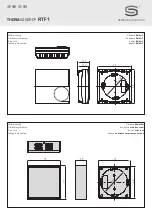
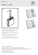
Mounting and Installation
G
Caution
You must ensure that the potentiometer is connected up correctly. Polarity reversal can cause a short circuit.