


G
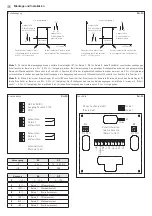
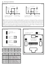
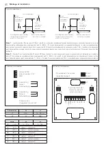
Mounting and Installation
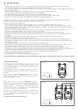
Switching output
RH - 30
W1
A1 B1
W1
A1 B1
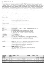
Hysteresis
3% r.H.
Switching output 1
Relative humidity
Gone
switchpoint
threshold
Preset
switchpoint
threshold
exeeded
Switching back when humidity
falls below preset limit value
with 3% r.H. hysteresis
Behaviour when preset
limit value is exeeded
below preset
W2
A2 B2
W2
A2 B2
Hysteresis
3% r.H.
Switching output 2
Relative humidity
Gone
switchpoint
threshold
Preset
switchpoint
threshold
exeeded
Behaviour when preset
limit value is exeeded
Switching back when humidity
falls below preset limit value
with 3% r.H. hysteresis
below preset
Connecting diagram
RH - 30
1
2
3
4
5
6
7
8
9
GND
UB 24V AC/DC
Humidifying
Relay 1
Dehumidifying
Humidifying
Relay 2
Dehumidifying
Potential-free
changeover contact 24V
Output humidity 0-10V
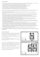
Schematic diagram
RH - 30
Supply
AC
DC
→ 1
24 V∼
15 ... 36 V DC
→ 3
0 V
GND
Output
AC
DC
2
→ (r. F.)
0 ... 10 V
0 ... 10 V
4
(A1) →
Relay 1 Breaker contact
5
(W1) →
Relay 1 Changeover contact
6
(B1) →
Relay 1 Normally open contact
7
(A2) →
Relay 2 Breaker contact
8
(W2) →
Relay 2 Changeover contact
9
(B2) →
Relay 2 Normally open contact
Mode 1:
Switch points for both relay outputs can be defined independent from each other in the range of 5 %... 95 % r. H. by turning control
knobs (R 1 for relay 1, R 2 for relay 2, see schematic diagram). When the respective switch point is exceeded, the corresponding relay switches
over (changeover contact W switches from position A to position B). When the preset switchpoint is undershot again by more than 3 % r. H.
(hysteresis), the respective switching output switches back to the initial position (changeover contact W switches from position B to position A).
Mode 2:
Only control knob R1 is active (R 2 without function)! The switchpoint for the first relay is defined in the range of 5 %... 95 % r. H.
by turning control knob R 1 (see schematic diagram). The switch point for the second relay output is in mode 2 invariably defined as "switch
point 1 + 5 % r. H." A hysteresis of 3 % r. H. is predefined for each switching output also in mode 2.
J1
1 2 3 4 5 6 7 8 9
5% 95%
R1
5% 95%
R2
+ UB
Output
GND
A1
W1
B1
A2
W2
B2
Mode 1
Mode
Mode 2
Switching thresholds
relative humidity for
relay 1 and relay 2
R2 extended to the outside
(adjustment wheel)
Summary of Contents for HYGRASREG RH-30
Page 16: ...HYGRASREG RH 30 D G F r...


