


F
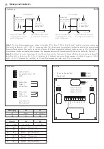
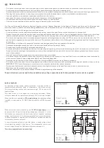
Montage et installation
Sortie de commutation
RH - 30
W1
A1 B1
W1
A1 B1
Hysteresis
3% r.H.
Switching output 1
Relative humidity
Gone
switchpoint
threshold
Preset
switchpoint
threshold
exeeded
Switching back when humidity
falls below preset limit value
with 3% r.H. hysteresis
Behaviour when preset
limit value is exeeded
below preset
W2
A2 B2
W2
A2 B2
Hysteresis
3% r.H.
Switching output 2
Relative humidity
Gone
switchpoint
threshold
Preset
switchpoint
threshold
exeeded
Behaviour when preset
limit value is exeeded
Switching back when humidity
falls below preset limit value
with 3% r.H. hysteresis
below preset
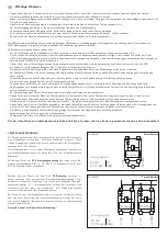
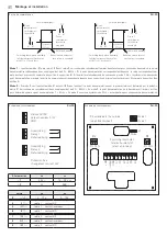
Schéma de raccordement
RH - 30
1
2
3
4
5
6
7
8
9
GND
UB 24V AC/DC
Humidifying
Relay 1
Dehumidifying
Humidifying
Relay 2
Dehumidifying
Potential-free
changeover contact 24V
Output humidity 0-10V
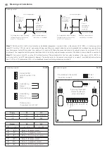
Schéma de raccordement
RH - 30
Alimentation
ca
cc
→ 1
24 V∼
15 ... 36 V cc
→ 3
0 V
GND
sortie
ca
cc
2
→ (r. F.)
0 ... 10 V
0 ... 10 V
4
(A1) →
relais 1 contact NF
5
(W1) →
relais 1 contact inverseur
6
(B1) →
relais 1 contact NO
7
(A2) →
relais 2 contact NF
8
(W2) →
relais 2 contact inverseur
9
(B2) →
relais 2 contact NO
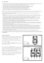
Mode 1 :
Le potentiomètre (R1 pour relais 1, R2 pour relais 2, voir schéma de raccordement) permet de déterminer pour chacun des deux relais des points
de commutation indépendants dans une plage allant de 5 % ... 95 % h.r.. Si le point de commutation correspondant est dépassé, le relais correspondant com-
mute (contact inverseur W commute de position A en position B). Si l’humidité relative descend de nouveau de plus de 3 % h.r. (hystérésis) au-dessous du
point de commutation préréglé, la sortie de commutation correspondante repasse dans sa position d’origine (contact inverseur W commute de position B en
position A).
Mode 2 :
En mode 2, seul le potentiomètre R1 est actif (R2 sans fonction) ! Le point de commutation pour le premier relais est déterminé par le potentio-
mètre R1 (voir schéma de raccordement) dans une plage allant de 5 % ... 95 % h.r.. En mode 2, le point de commutation de la deuxième sortie relais est tou-
jours déterminé comme « point de commutation 1 + 5 % h.r. ». En mode 2 aussi, une hystérésis de 3 % h.r. est prédéfinie pour chaque sortie de commutation.
J1
1 2 3 4 5 6 7 8 9
5% 95%
R1
5% 95%
R2
+ UB
Output
GND
A1
W1
B1
A2
W2
B2
Mode 1
Mode
Mode 2
Switching thresholds
relative humidity for
relay 1 and relay 2
R2 extended to the outside
(adjustment wheel)
Summary of Contents for HYGRASREG RH-30
Page 16: ...HYGRASREG RH 30 D G F r...


