G
THERMASGARD
®
RTF 1
Type ⁄ WG1
Item No.
Output
RTF1 Pt100
THERMASGARD–4030–1000–000
Pt100
RTF1 Pt1000
THERMASGARD–4030–5000–000
Pt1000
RTF1 Ni1000
THERMASGARD–4030–9000–000
Ni1000
RTF1 Ni1000 TK5000
THERMASGARD–4031–0000–000
Ni1000 TK5000, LG - Ni1000
RTF1 NTC 1.8k Ohm
THERMASGARD–4031–2000–000
NTC 1.8k Ohm
RTF1 NTC 20k Ohm
THERMASGARD–4031–6000–000
NTC 20k Ohm
RTF1 NTC 10k Ohm
THERMASGARD–4031–5000–000
NTC 10k Ohm
RTF1 NTC 10k Pre
THERMASGARD–4031–9000–000
NTC 10 k Pre
RTF1 KTY 81-210
THERMASGARD–4032–0000–000
KTY 81-210
RTF1 LM235Z
THERMASGARD–4132–1000–000
LM235Z (TCR = 10 mV ⁄ K; 2.73 V at 0 °C), KP10
RTF1 S-24
THERMASGARD–4175–0000–000
RS 485 (S-Bus)
RTF1 Enclosure, empty
7000–4030–0000–000
–
RTF1 Stainless steel enclosure
–
–
RTF1 xx - Display
–
Ω rating, display (0 ⁄ +50°C)
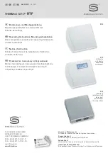
Room temperature sensor THERMASGARD
®
RTF 1 with passive output, optional
with or without display for displaying the actual temperature in an elegant enclosure
made of plastic, with snap-on lid, base with 4-hole attachment for installation on
vertically or horizontally installed in-wall flush boxes, with predetermined breaking
point for on-wall cable entry, or in enclosures made of stainless steel (top and bot-
tom part are of stainless steel, the lid is screwed on), vandalism-secure version e.g.
for schools, military barracks, and public buildings. This residential room tempera-
ture sensor is used to detect ⁄ display temperatures in closed dry rooms, in apart-
ments, in cinemas, supermarkets, storage rooms, office and business facilities.
TECHNICAL DATA:
Measuring range: ....................... - 30 ...+ 90 °C
Sensor ⁄ output: .......................... see table, passive or bus signal
Connection type: ........................ 2-wire connection
Testing current: .......................... ca. 1 mA
Process connection: .................. by screws
Enclosure: .................................... plastic, material ABS,
colour pure white (similar RAL 9010),
optional stainless steel
Dimensions: ................................. 85 x 91 x 27 mm (Frija I)
Installation: .................................. wall mounting or on in-wall flush box Ø 55 mm,
base with 4-hole for mounting on vertically or
horizontally installed in-wall flush boxes for cable
entry from the back, with predetermined breaking
point for on-wall cable entry from top ⁄ bottom in
case of plain on-wall installation
Electrical connection: ................ 0.14 - 1.5 mm² via terminal screws,
on safety extra-low voltage max. 24 V DC only
Humidity: ...................................... max. 90 % r. H., non-precipitating air
Protection class: ........................ III (according to EN 60 730)
Protection type:.......................... IP 30 (according to EN 60 529)
Optional: ....................................... 8-digit display,
cutout 36 x14 mm (W x H),
for displaying actual temperature
Circuit diagram
RTF 1
with display
1
2
21
20
min. max.
Correction T
int.
Sensor
ext.
Sensor
Connecting diagram
RTF 1
with display
1
2
21
20
UB+ supply voltage 24V DC
UB- GND
Rx
1x two-wire connection
RTF 1
standard
1x two-wire connection
RTF 1
LM 235 Z (KP 10)
Summary of Contents for Frija I Series
Page 30: ...r ZVEI VDE EMV...


