


20
F
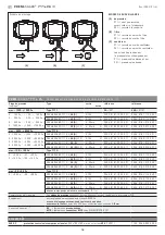
PREMASGARD
®
711x
Interrupteurs DIP 4 et 6 non affectés!
PREMASGARD
®
711x - I
PREMASGARD
®
711x - I
Interrupteurs DIP 4 et 6 non affectés!
PREMASGARD
®
711x - U
PREMASGARD
®
711x - U
1
2
3
AUTO
ZERO
SET
min. max.
OFFSET
1 2 3 4 5 6
ON DIP
+UB 24V AC / 15...36V DC
Output pressure 0-10V [Pa]
–UB GND
Plug for
display
Offset correction
ca. ±10 % of final value
Pushbutton
Zero point setting
Cont
act
pin side
SET-Setting Cycle time
(autom. zero point calibration)
1
2
3
AUTO
ZERO
SET
min. max.
OFFSET
1 2 3 4 5 6
ON DIP
+UB 15...36V DC
Output pressure 4...20mA [Pa]
–UB GND
(LCD backlighting / automatic
zero point calibration)
Plug for
display
Offset correction
ca. ±10 % of final value
Pushbutton
Zero point setting
Cont
act
pin side
SET-Setting Cycle time
(autom. zero point calibration)
Affectation des plots
de connexion (M12)
Affectation des plots
de connexion (M12)
Schéma de raccordement
Schéma de raccordement
1
2
3
4
5
45°
1
2
3
4
5
–UB GND (LCD backlighting /
automatic zero point calibration)
+UB 15...36V DC
Output pressure 4…20mA [Pa]
free
Shield
1
2
3
4
5
45°
1
2
3
4
5
–UB GND
+UB 24V AC / 15...36V DC
Output pressure 0 -10V [Pa]
free
Shield
# 502
00 - 2020


