


SWITCH BOX
15
Switch Box Familiarization
The purpose of this section is to familiarize the user with
the operation of the switch box BEFORE the router is
plugged in.
WARNING:
DO NOT plug the router in at this time. An ON switch
will start and an unprepared user could possibly be
seriously injured.
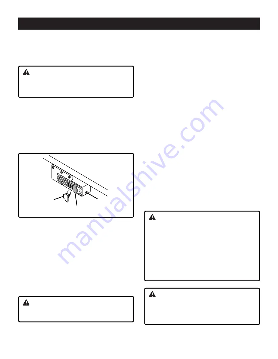
See Figure 15
The switch box also features a safety key that prevents
tools plugged into the switch box from being turned ON
inadvertently. Removal of the safety key disables the
switch box by locking the switch in the OFF position.
Strike the switch paddle with your hand to turn the router
OFF in an emergency situation. Please note paddle switch
positions and reset button at this time.
Fig. 15
reset button
safety key
paddle switch
Operation of Switch Box and Router
Make sure router switch is OFF and switch box is OFF
BEFORE proceeding.
1. Insert the yellow safety key into the switch box.
2. Position router power switch to ON.
NOTE: If your router requires the use of the switch trigger
and "Lock-On" button, refer to your Router Owner's
Manual for operating instructions.
3. Insert finger under paddle and pull switch to ON
position.
4. To turn router OFF, push paddle down.
WARNING:
Router bit must come to a complete stop before
leaving router table unattended.
5. Lock switch to OFF position by removing key from
switch box.
For Routers With "LOCK-ON" Feature
The "LOCK-ON" feature will not permit the router to be
turned ON by the switch box, but it can be turned OFF by
the switch box. Operate as follows:
1. Place the switch box to ON as previously described.
The router should NOT start even though the trigger
lock is in the "LOCK-ON" position. Refer to your Router
Owner's Manual.
2. To start router, depress trigger and engage "LOCK-ON"
button. Router should start.
NOTE: The router will not start if the router switch is
al-ready in the "LOCK-ON" position. In this case, unlock
the trigger, depress the trigger to start the router, then
reengage the "LOCK-ON" button.
3. To turn router OFF, push switch paddle down.
Circuit Breaker
If an overload occurs, the circuit breaker inside the
switch box trips and interrupts power to the router and any
accessories. If this happens:
1. Unplug the power cord.
2. Remove the workpiece from the router bit and table.
3. Find the cause of the overload and correct.
4. Push the reset button to reset it.
See Figure 15
.
5. Plug in power cord.
6. Follow instructions under Operation of Switch Box and
Router to reset router.
WARNING:
When router table is not in use, always:
1. Place the switch box in OFF position and remove
the safety key.
2. Place router power switch in OFF position.
3. Unplug switch box from wall outlet.
4. Remove router bit.
5. Make sure router collet assembly is below router
table.
6. Remove and place safety key in a secure location.
Remember where you place the safety key.
WARNING:
If breaker trips, or the router stalls, or if the power fails
for any other reason, place the switch box in the OFF
position, remove the safety key, and unplug the switch
box from the wall outlet.
Bdal 6144.461 3Sprachen 04.06.2005 11:56 Uhr Seite 15
Summary of Contents for RT401W
Page 23: ...Notes 23...