


3
trigger using finger pressure.
In addition, fastener driving tool is fitted with a safety
yoke which enables the driving operation to be carried
out only after the safety yoke of the tool is pressed
against a work piece, These tools are marked with an
inverted triangle behind the serial number and are
not permitted for use without an effective safety yoke.
A safety yoke is not required on fastener driving tools
which accelerate the heaviest usable fasteners to a
free flight velocity below an admissible risk of injury.
Those fastener driving tools are not marked with an
inverted triangle.
SAFEty INStRUctIONS FOR cOMpRESSEd AIR
SyStEM
■ Proper functioning of the fastener driving tool requires
filtered, dry and lubricated compressed air in adequate
quantities.
■ If the air pressure in the line system exceeds the
maximum allowable pressure of the fastener driving
tool, a pressure reducing valve followed by a
downstream safety valve shall additionally be fitted in
the supply line to the tool.
■ The compressor plant shall be adequately
dimensioned in terms of pressure output and
performance (volumetric flow) for the consumption
which is to be expected. Line sections which are too
small in relation to the length of the line (pipes and
hoses), as well as overloading the compressor, will
result in pressure drops.
■ Permanently laid compressed air pipelines should
have an internal diameter of at least 19 mm and a
corresponding large diameter where relatively long
pipelines or multiple users are involved.
■ Compressed air pipelines should be laid so as to
form a gradient (highest point in the direction to the
compressor). Easily accessible water separators
should be installed at the lowest points.
■ Junctions for users should be joined to the pipelines
from above,
■ Connecting points for fastener driving tools should be
fitted with a compressed air servicing unit (filter/water
separator/oiler) directly at the junction point.
RESIdUAl RISkS
Even if you are operating this product in accordance
with all the safety requirements, potential risks of injury
and damage remain. The following dangers can arise in
connection with the structure and design of this product:
1. Health defects resulting from vibration and noise
emission if the product is being used over long periods
of time or not adequately managed and properly
maintained.
2. Injuries and damage to property due to fasteners or
the sudden impact of hidden objects during use.
3. Danger of injury and property damage caused by
flying objects.
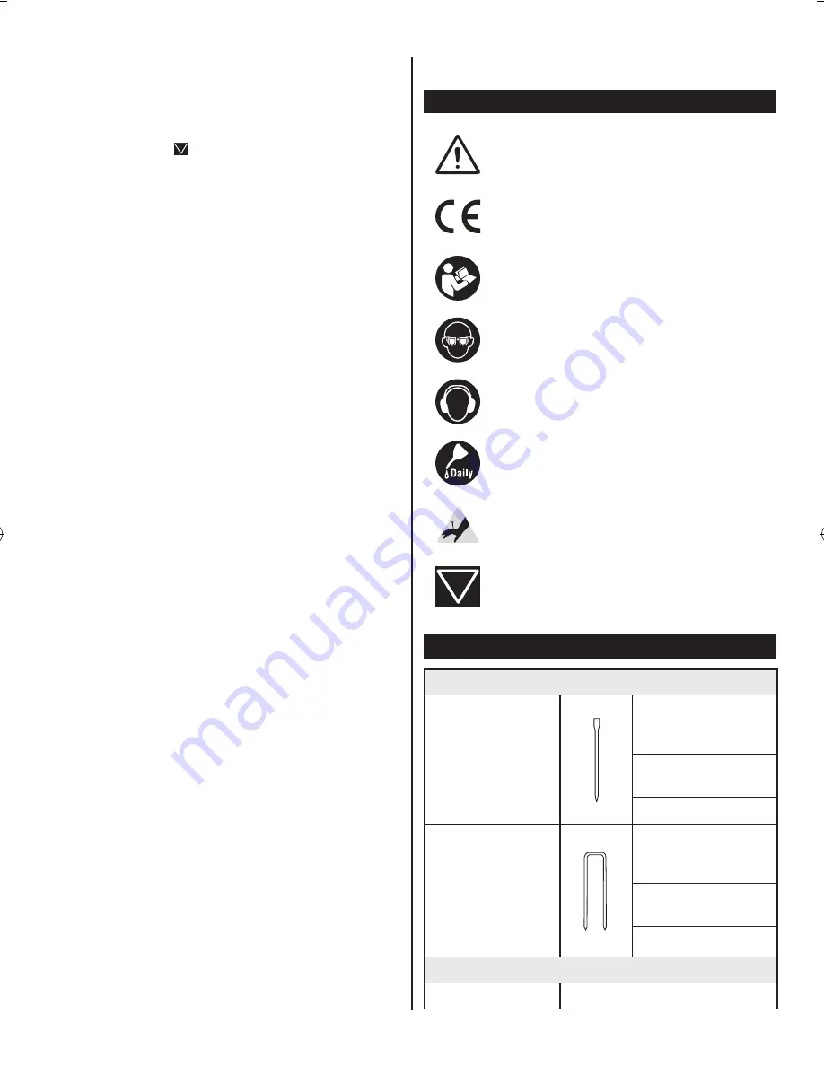
SyMBOlS
Safety alert
CE conformity
Please read the instructions carefully before
starting the product.
Wear eye protection.
Wear ear protection.
Lubricate with air tool oil daily.
Keep hands away
Tacker with safety yoke
SpEcIFIcAtIONS
FAStENER
Nail type
C1 series brad nails
- 1.25mm
(18 Gauge)
Nail range:
15 - 32 mm
Collation angle: 0°
Staple type
6000 series narrow
crown staples –
1.25 mm (18 Gauge)
Nail range:
16 - 32 mm
Collation angle: 0°
tOOl
Magazine capacity
100 nails/staples


