background image

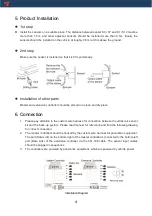
5. Product Installation

1st step

Install the sensors on a suitable place. The distance between sensor S6 / S7 and S1 / S12 must be

more  than  1.5m,  and  other  adjacent  sensors  should  be  installed  more  than  0.5m.  Ideally  the

sensors should be installed on the vehicle at roughly 0.6m to 0.8m above the ground.

2nd step

Make sure the sensor is installed so that it is firm and steady.

Installation of other parts

Master and extension controller should be placed in a clean and dry place.

6. Connection

1.

Please pay attention to the custom wire harness for connection between the ultrasonic sensor

kit and the back-up system. Please read manual for reference and find the following drawing

for correct connection.

2.

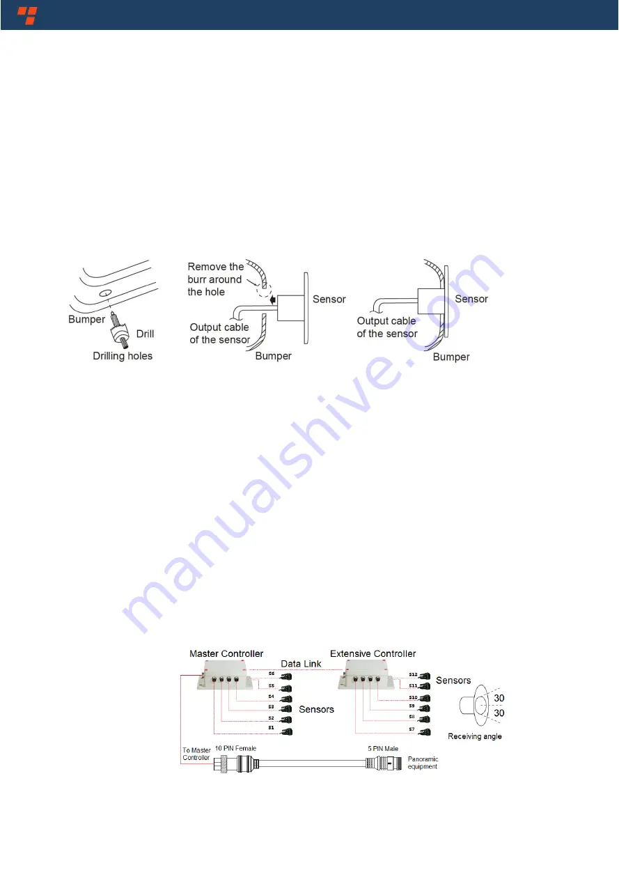
The master controller should be hooked by the custom wire harness for panoramic equipment.

The port (Data Link) on the bottom-right


of the master controller is connected to the bottom-left

port  (Data  Link)  of  the  extension  controller  via  the  461-10#  cable.  The  sensor  input  cables

should be plugged in sequences.

3.

The controllers are powered by panoramic equipment, which are powered by vehicle power.

Installation Diagram 

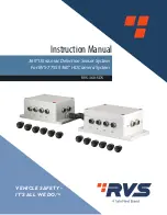
Summary of Contents for RVS-360-SDS

Page 1: ...360 Ultrasonic Detection Sensor System For RVS 77555 360 HD Camera System RVS 360 SDS Instruction Manual VEHICLE SAFETY IT S ALL WE DO TM ...

Page 2: ...Contents 1 Precautions 1 2 Hints for Users 3 3 Specifications 3 4 Product Features 3 5 Product Installation 4 6 Connection 4 7 Troubleshooting 6 ...

Page 3: ...nnected properly Observe polarity Improper cable connections may damage the device 3 Testing and inspection of the system in accordance with these instructions and a record of the results should be listed on the daily maintenance report The units on operating vehicles must be tested each day prior to the vehicle s operation Results of this test must be recorded in the maintenance log 4 Proper inst...

Page 4: ...er serviceable parts inside Refer servicing to qualified service personnel CAUTION You are cautioned that any changes or modifications not expressly approved in this manual could void your warranty and necessitate repairs This symbol is intended to alert the user to the presence of uninsulated dangerous voltage within the product s enclosure that may be of sufficient magnitude to constitute risk o...

Page 5: ...ditions while reversing 4 There may be improper reception deviation and error in reflected signal because of difference in material angle or size of obstacles 3 Specifications 1 Number Of Sensors 12 PCS 2 Color Of Sensors Black default Optional 3 Ultrasonic Frequency 40KHz 4 Detecting Distance 0m 5 00m for each sensor 5 Power Supply DC10 18V 6 Operating Temperature 20 70 RH90 Max 7 Storage Tempera...

Page 6: ...clean and dry place 6 Connection 1 Please pay attention to the custom wire harness for connection between the ultrasonic sensor kit and the back up system Please read manual for reference and find the following drawing for correct connection 2 The master controller should be hooked by the custom wire harness for panoramic equipment The port Data Link on the bottom right of the master controller is...

Page 7: ...5 461 10 cable Notice Most problems occurred in testing are usually caused by improper installation of the sensors they may be solved in actual application ...

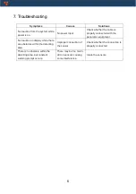
Page 8: ... with the panoramic equipment No reaction on display while there are obstacles within the detecting area Improper connection of the sensor Check whether the connection is properly connected There is no obstacle within the detecting area but constant warning prompt occurs There may be too much dirt on sensors causing some interference Clean the sensors ...

Page 9: ...If you have any questions about this product contact RearViewSafety Inc 1797AtlanticAvenue Brooklyn NY11233 800 764 1028 VehicleSafety It sAllWeDo TM ...

Reviews: