


41
CAHA Midi
Installation, Usage and Maintenance Instructions
7.2 ADJUSTMENT % CO
2
AND CHECK INPUT
The boiler is equipped with an automatic gas/air regulator. This means that the amount of gas is regulated depending on
the amount of air. The % CO2 needs to be adjusted according to the table below ;
Type of boiler
Gas type
Inlet pressure
%CO
2
on max load
%CO
2
on min load
340
G20 / G25
20 / 25 mbar
9.3 +0.2-0.05
9.1 +0.15-0.2
425
G20 / G25
20 / 25 mbar
9.3 +0.2-0.05
9.1 +0.15-0.2
510
G20 / G25
20 / 25 mbar
9.3 +0.2-0.05
9.1 +0.15-0.2
600
G20 / G25
20 / 25 mbar
9.3 +0.2-0.05
9.1 +0.15-0.2
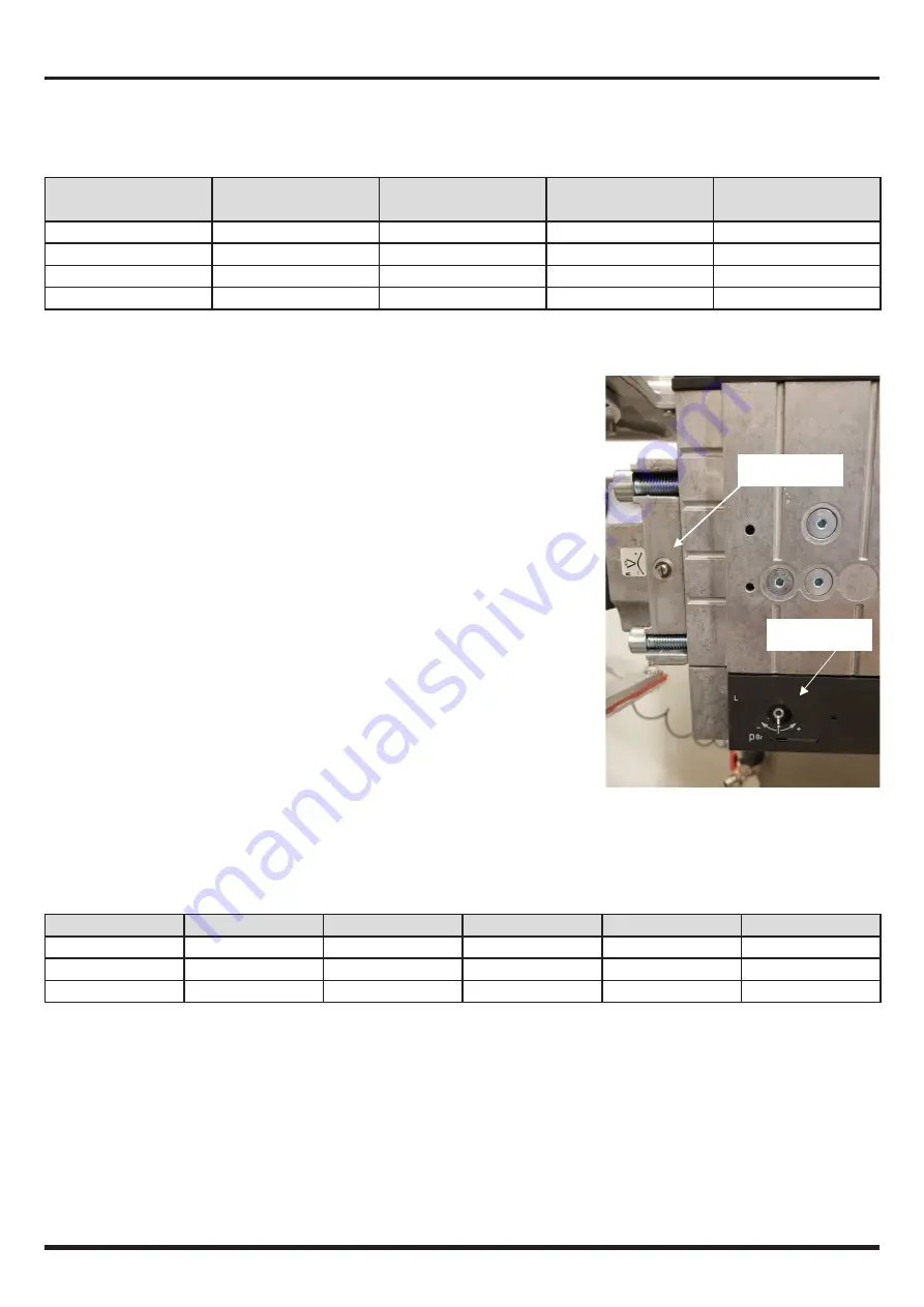
The boiler has a gas valve that is connected to a venturi. See figure below.
ADJUSTMENT FOR MAX. LOAD
• Wait until the boiler is stable and measure % CO
2
• If required, correct CO
2
with the throttle ; turning t gives a higher
CO
2
percentage (a ½ turn (180°) causes a change of approximately 0,85 %
CO
2
)
•
ADJUSTMENT FOR MIN. LOAD
• Wait until the boiler is stable
• If required, correct the CO
2
with the off-set ; turning t gives a higher
CO
2
percentage. Note : this offset adjustment is very sensitive : half a turn
(180°) causes a change of approximately 1 % CO
2
.
CHECK ON HEAT INPUT
In the table below the relationship between nominal input and fan speed and gasflow is given. The nominal fan speed can
be ± 5% due to adjustments in production
Model
340
425
515
600
Nominal input
340
425
515
595
[kW Hi]
Fan speed nominal
4600
4600
4600
4600
[rpm]
Gasflow G20
36
45
54
63
[m3/h]
If the gas flow is too low it may be due to an obstruction (dirt) in the air/flue system. Check and if necessary clean. The gas
flow must then be re-checked.
Throttle
Off-set