RUTHMAN GUSHER PUMPS 7600 H Series Manual Download Page 7

8

It is necessary that the rings be cut to the correct size, 
otherwise service life is reduced. 

4. Install one ring at a time. Make sure it is clean and 
has not picked up any dirt in handling. If clean oil is  
available,  lubricate  the  shaft  and  the  inside  of  the  
stuffing box. 

Seat rings firmly. (Except for TFE filament and graph-
ite yarn packings which should be snugged up very 
gently.  Then  wrench  in  gradually...after  the  pump  is 
back in operation.) Joints of successive rings should 
be staggered and kept at 90

O

  apart. Each individu-

al  ring  should  be  firmly  seated  with  a  tamping  tool. 
When enough rings have been individually seated so 
the nose of the gland (#9) will reach them, individual 
tamping should be supplemented by the gland. Nev-
er depend entirely on the gland to seat a set of rings 
properly - this practice will jam the last rings installed 
but leave the bottom rings loose in the box.

5. After the last ring is installed take up bolts finger 
tight  or  very  slightly  snugged  up.  Do  not  jam  the 
packing into place by excessive gland loading. Start 
pump, and take up bolts until leakage is decreased to 
minimum. Make sure gland bolts are taken up evenly, 
stopping leakage entirely at this point will cause the 
packing to burn up.

6. 

Allow packing to leak freely when starting up a newly


packed pump. Excessive leakage during the first hour 
of operation will result in a better packing job over a 
longer  period  of  time.  Final  adjustment  should  allow 
approximately  30  drops  per  minute  to  leak  from  the 
packing. 

7. When specified, Gusher can provide means of lu-
bricating the shaft and packing through a lantern ring 
by supplying water, oil, grease, or liquid handled in the 
pump. 

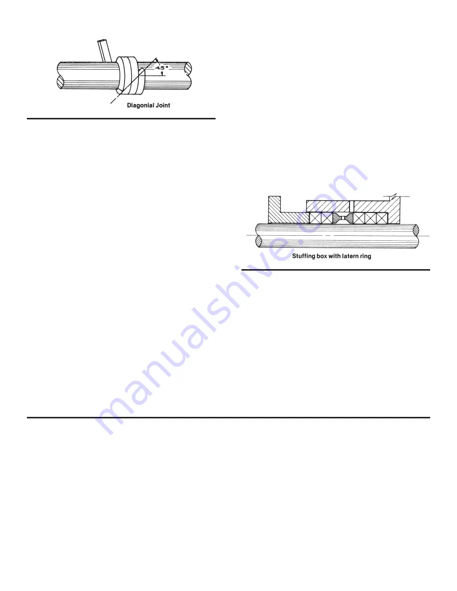
8. If the stuffing box has a lantern ring, make sure the 
lantern ring, as installed, is slightly behind the fluid inlet 
so it will move under the inlet as gland pressure is ap-
plied. (See illustration below.)

9.  Replace  packing  when  leakage  cannot  be  con-
trolled by further takeup on the gland.

Some of the most common reasons for packing failure 
are:

1.  Improper installation
2.  Uneven gland adjustment
3.  Shaft misalignment and shaft whip
4.  Improper selection of packing for liquid
5.  Improper selection for pressure and temperature
6.  Contaminated liquid (dirt, abrasives, etc.)

MECHANICAL SEAL


The most important factor in mechanical seal, other than 
the sealing qualities, is the fact that once it has been prop-
erly installed there is little or no maintenance required.

Some of the most common reasons for seal failure are:
1.  Improper installation
2.  Shaft misalignment and shaft whip

3.  Wrong selection for liquid pumped
4.  Wrong selection for pressure and temperature
5.  Dirt or grit between faces
6.  Seal gland (#9) tightened unevenly so stationary seat 

is not perpendicular to shaft.

7.  Operation without fluid

Summary of Contents for GUSHER PUMPS 7600 H Series

Page 1: ...ruction manual instruction manual 7600 H and 7650 H SERIES GUSHER PUMPS INC 115 INDUSTRIAL DRIVE WILLIAMSTOWN KY 41097 PHONE 859 824 3100 FAX 859 824 7428 www gusher com MAINTENANCE INSTALLATION OPERATIONS ...

Page 2: ...iption Chart 13 Cross Sectional Drawings 14 18 Maintenance History 19 Engineering Data 19 WARRANTY Gusher Pumps Inc will replace or repair within one year of shipment from our plant any pump in our judgement that has failed due to defects in materials or workmanship provided the pump has been properly installed and maintained and has not been subject to abuse These pumps must return to Gusher Pump...

Page 3: ...the pump should be located as near the source of supply as possible Allow ample room for inspection and maintenance If your pump is not going to be installed within six months several precautions must be taken 1 Preservative treatment of bearings and machined surfaces is required 2 Remove packing on pumps with packed stuffing box the stuffing box and shaft sleeve must be oil lubricated to also pro...

Page 4: ...s points around the periphery of the coupling DO NOT rotate the coupling If offset ex ceeds 010 re align the coupling See Fig 3 Check angular alignment with micrometer or caliper Measure from the outside of the one flange to the outside of the other flange at intervals around the periphery of the coupling DO NOT rotate the coupling The difference between the maximum and minimum must not exceed 010...

Page 5: ...n line must be tight for proper oper ation of the pump Install a gate valve in discharge line as close to the pump as possible see Fig 6 If a foot valve is not used in the suction line it is good practice to bell out suction pipe to lower the entrance velocities at the inlet Fig 8 Whenever possible the end of the suction should be a minimum of 3 below the low liquid level Fig 8 The liquid near the...

Page 6: ...ted at the Gusher Plant and should not require additional lubrication for approximately 1200 hours of operation A well planned maintenance schedule can only be devised after the first six months of operation and the lubrication record re view at that time Each pump installation is unique and requires individual attention to set up the proper lubrica tion schedule for each specific installation Abo...

Page 7: ...y packed pump Excessive leakage during the first hour of operation will result in a better packing job over a longer period of time Final adjustment should allow approximately 30 drops per minute to leak from the packing 7 When specified Gusher can provide means of lu bricating the shaft and packing through a lantern ring by supplying water oil grease or liquid handled in the pump 8 If the stuffin...

Page 8: ...r 12 does not rub intake flange 25 or impeller hous ing 11 If impeller does rub repeat steps 1 through 7 Fig 9 RECOMMENDED SPARE PARTS If a spare pump cannot be justified Gusher recommends several parts be kept in your stock for emergency situations We recommend 1 Mechanical Seal 2 Set of Packing 3 Impeller 4 O rings 5 Drive Key 6 Gaskets 7 Ball Bearings 8 Shaft Sleeve 9 Oil Seals 10 Impeller Reta...

Page 9: ...pressed onto it by ram pressure against a piece of soft metal tubing as shown in Fig 11 The tubing must be clean inside and out and the inside diameter of the tubing should be slightly greater than the bearing bore The ends of the tubing should be square with corners chamfered to avoid flaking and should contact only the bearing inner ring The shaft must be held in line with the ram of the arbor p...

Page 10: ...ll 9 Foot valve too small 10 Foot valve or suction opening not submerged deep enough NOT ENOUGH PRESSURE 1 Speed too low 2 Air in water 3 Mechanical defects Wear ring is worn Impeller damaged 4 Impeller diameter too small VIBRATION 1 Bent shaft 2 Pipe strain 3 Impeller clogged 4 Coupling alignment off PUMP WORKS FOR A WHILE AND THEN LOSES SUCTION 1 Leaky suction line 2 Water seal plugged 3 Impelle...

Page 11: ...8 from stem 7 Unbolt stem plate 18 from seal packing gland 9 Remove stem plate On packed pumps the pack ing 28 and shaft sleeve 20 Usually will come off with the stem plate 3 Remove shaft sleeve 20 from shaft 1 Me chanical seal 23 will come off with shaft sleeve 20 Remove seal 23 from sleeve 20 4 Remove packing 28 and shaft sleeve 20 from either shaft 1 or stem plate 18 5 Remove seal packing gland...

Page 12: ...Seal Gland Cartridge Impeller Housing Impeller Cartridge O ring Oil Seal Shaft Sleeve Gasket Bearing Retainer Gasket Packing Seat Washer Stem Plate Ball Bearing Housing Shaft Sleeve Oil Breather Oil Seal Mechanical Seal Steam Plate Gasket Intake Flange Impeller Lock Nut Intake Flange Gasket Packing Pedestal Seal Gland Gasket Impeller Housing Bracket Coupling see page 9 Coupling Sleeve see page 9 D...

Page 13: ...14 51H 52H POWER FRAME No Shaft Sleeve 51H 52H POWER FRAME With Standard Impeller Retaining Bolt ...

Page 14: ...15 51H 52H POWER FRAME With Special Impeller Lock Nut 7071M POWER FRAME With Special Impeller Lock Nut ...

Page 15: ...16 Center Line Housing With 7071L POWER FRAME ...

Page 16: ...17 7071S POWER FRAME Threaded Impeller For 7071S 7071M 7071L POWER FRAME ...

Page 17: ...18 CLOSE COUPLED STYLE ...

Page 18: ...____________________ ENGINEERING DATA POWER FRAME 51H 52H 7071S 7071M 7071L 1 RADIAL BRG 41207 41209 41207 41309 41313 2 THRUST BRG 41307 41309 41306 DR 41309 DR 41313 DR 3 BALL BRG SPAN 6 748 8 897 4 124 6 868 9 242 4 SHAFT DIA S RADIAL BRG 1 378 1 771 1 378 1 771 2 559 THRUST BRG 1 378 1 771 1 181 1 771 2 559 COUPLING 1 249 1 499 874 1 124 2 374 OIL CAPACITY OF POWER FRAMES 51H 1 1 4 pt approx 5...

Page 19: ...al turbine pumps positive displacement pumps gear pumps and other specialized pump equipment while upholding its reputation as a leader in the custom engineering of pumps for the most challenging applications RC 0 20 www Gusher com GUSHER PUMPS LOCATIONS Williamstown Headquarters 115 Industrial Road Williamstown KY 41097 Phone 859 824 5001 Fax 859 824 3011 Email Info Gusher com Dry Ridge Manufactu...

Reviews: