Step-by-Step InSTrUCTIonS
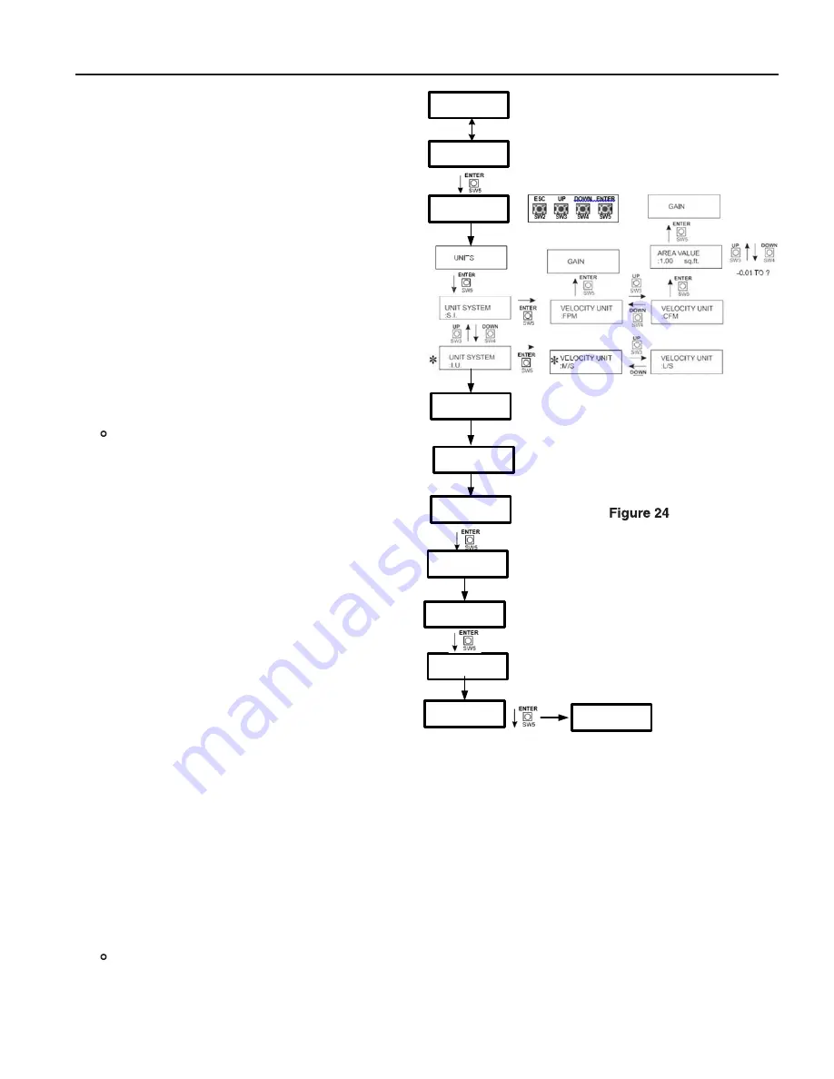
(see Figure 24)
When power is applied for the first time the display
will first show firmware revision number and then the
display will eventually read “INITIAL STARTUP FIELD
CALIBRATE” and alternately read “HOLD ENTER KEY
COMPLETE SETUP” (If this is NOT displayed then
see SETUP AND ADJUSTMENTS, RESET SETTINGS,
select UNITS and then scroll to BALANCER FIELD CAL-
IBRATION and select ON.)
• When the “ENTER” button is depressed the display
will read “FIRST STEP SETUP UNITS.”
• Depress “ENTER” and use the ESC UP DOWN and
ENTER buttons, when “UNITS” is displayed to se-
lect desired units for calibration to match T&B units.
“GAIN” is always 1 and the area is the total area
through the fan inlet(s).
• After units have been selected the transmitter will
show “SECOND STEP CALIBRATION” briefly and
then show “RUN FAN MINIMUM SPEED” followed
by “MIN FLOW POINT” continuously.
At this point the fan must be running at the first
flow or the minimum fan speed or lowest operat-
ing point for the system. Note: The point must
be on the fan curve and not simply the lowest
speed the variable speed drive is able to run. This
point is typically between 15HZ and 30 HZ even
though the VFD might be able to run slower. Air
flow values below the minimum operating point
on the fan curve stir the air but may not move any
air and will produce poor calibration results.
• With air passing across the sensors at the minimum
air flow, adjust the transmitter display using the up
and down buttons until the value displayed matches
the known air flow at this fan speed and press the
“ENTER” button.
• The display will briefly display “RUN FAN MIDDLE
SPEED” followed by “MID FLOW POINT” continu-
ously. Increase the fan speed to the second op-
erating air flow point. With air passing across the
sensors at the middle speed, adjust the transmitter
display using the up and down buttons until the
value displayed matches the known air flow at this fan speed and press the “ENTER” button.
• The transmitter will briefly display “RUN FAN MAXIMUM SPEED” followed by “MAX FLOW POINT” continuously.
Increase the fan speed to the maximum expected operating air flow. With air passing through the sensors at the
maximum expected operating air flow, adjust the transmitter display using the up and down buttons until the
value displayed matches the known air flow at this fan speed and press the “Enter” button. The transmitter dis-
play will show “CYCLE POWER” and will automatically cycle or can be turned off and backed on to enter normal
operating mode. DO NOT TURN OFF BALANCER FIELD CALIBRATION MODE.
• Turn the fan off and close any dampers to prevent any air movement through the fan. With no air passing through
the fan or the fan blocked off, use the up or down button to scroll through each sensor and note highest value
displayed.
• Use the ZERO CUTOFF feature to enter a value greater than the highest value displayed on any one sensor.
Please NOTE: Previous balancer settings are lost when the field calibration mode is turned off.
To repeat the calibration steps again the field calibration mode can be turned off and then on again to
repeat the setup steps using fan speeds and conditions previously established as known air flow values for
low, medium and high.
INITIAL STARTUP
FIELD CALIBRATE
HOLD ENTER KEY
COMPLETE SETUP
FIRST STEP
SETUP UNITS
SECOND STEP
CALIBRATION
RUN FAN
MINIMUM SPEED
MIN FLOW POINT
?????
MID FLOW POINT
?????
RUN FAN
MIDDLE SPEED
MAX FLOW POINT
?????
RUN FAN
MAXIMUM SPEED
CYCLE POWER
rUSKIn EFAMS ThErMAl DISpErSIon AIrFlow MEASUrIng SYSTEM InSTAllATIon InSTrUCTIonS
9


