Runco Signature Cinema SC-1 Owner'S Operating Manual Download Page 110

Maintenance and Troubleshooting

98

Runco SC-1 Owner’s Operating Manual

PRE

L

IMINAR

Y

Error Codes

If the status code display on the back of the projector shows one of the following values, 
you have encountered a likely system error requiring the attention of a qualified service 
technician. Acknowledge and clear the error by pressing 

EXIT

 twice on the rear-panel 

keypad. Try resetting the projector by powering it off, allowing it to cool and powering it on 
again. Refer to Table 5-2 and contact your dealer if the problem persists. 

The specific code number identifies the source of the error detected, and is particularly 
useful in cases where the projector is far away. For example, the code “27” means the 
lamp could not be turned on.  
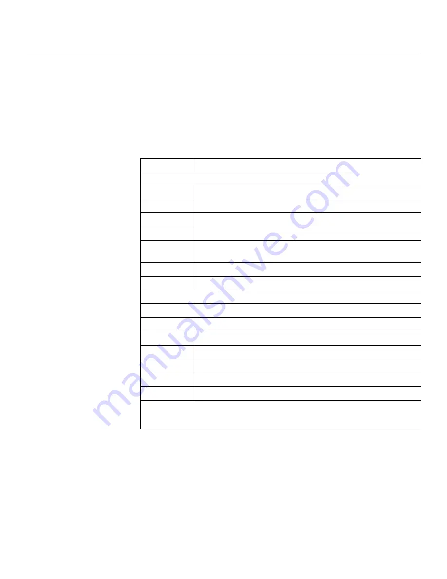
Table 5-2. 

S

C-1 Error Code

s


Code

De

s

cription

G

eneral

12

Software bug. Contact dealer or Runco Technical Support. 

13

CRC error in flash ROM. Download new software. 

14

Engineering-only programming is complete. Contact Runco, replace TIPM. 

15

Attempting to download code without being in boot mode. 

16

Invalid interrupt. Power off/on. If it persists, contact dealer or Runco Technical 
Support. 

17

User forced system to stay in boot mode. 

18

Jumper for programming boot not installed. 

Lamp Failure

s

20

Lamp turned on unexpectedly (fault related to ballast). 

22

One or more high-current lamp cables is not connected. 

26

Lamp 1 Interlock: lamp door open, lamp not installed. 

27

Can’t turn lamp on. 

28

Lamp turned off unexpectedly. 

29

Lamp ballast overheated. 

2C

Lamp communications fault; ballast is not detected. 

Note: 

To clear a system error, press the 

EXIT

 key (on the SC-1 control panel) twice. If necessary, 

reset the projector by powering it off, allowing it to cool and powering it on again. Contact your 
Runco dealer or Runco technical support if the error persists. 

Summary of Contents for Signature Cinema SC-1

Page 1: ...OWNER S OPERATING MANUAL SC 1 Three Chip Digital Light Processing Projector and Digital High Definition DHD Controller...

Page 2: ......

Page 3: ...normal use and does not cover normal maintenance This Limited Warranty does not cover cabinets or any appearance items failure resulting from accident misuse abuse neglect mishandling misapplication f...

Page 4: ...ment of the product for repair These arrangements must be made through the selling Runco Dealer If this is not possible contact Runco directly for a Return Authorization number and shipping instructio...

Page 5: ..._ ________________________________________ Model Purchased Date ____________________________________________________________________________________________________________ Serial Number _____________...

Page 6: ...r only outputs DC 12V signal for triggering Do not connect to any other power input or output This could cause damage to this unit 10 Only use accessories specified by Runco International 11 Keep the...

Page 7: ...d Benefits 4 Parts List 4 2 Controls and Functions 5 SC 1 at a Glance 5 SC 1 Input Panel 7 SC 1 Control Panel 9 DHD Controller Front Panel 11 DHD Controller Rear Panel 12 Outputs 12 Inputs 12 SC 1 Rem...

Page 8: ...e DHD Controller to the SC 1 32 Connecting Source Components to the DHD Controller 34 RS 232 Controller Connection 38 Connecting 12 volt Trigger Outputs to External Equipment 38 Connecting an External...

Page 9: ...g the On Screen Menus 69 Main Menu 71 Input Source 71 Aspect Ratio 71 Picture 74 Input Position 78 ISF Presets 79 Information 79 Calibration 80 Service 82 5 Maintenance and Troubleshooting 87 Safety G...

Page 10: ...t 91 Lamp Replacement 91 Filter Replacement 95 Lens Replacement 95 Troubleshooting Tips 96 Error Codes 98 6 Serial Communications 101 RS 232 Connection and Port Configuration 101 Serial Command Syntax...

Page 11: ...29 3 9 Adjusting the Feet 29 3 10 AutoScope Lens Motor with Extension Bracket 30 3 11 SC 1 with AutoScope Lens Motor Bottom View 30 3 12 Tilt Ranges Front to Back and Side to Side 31 3 13 Connecting...

Page 12: ...DHD Controller OSD Menu Structure for SC 1 70 4 2 Typical PLUGE Pattern for Adjusting Brightness 75 4 3 Typical Gray Bar Pattern for Adjusting Contrast 76 4 4 Typical Color Bar Pattern for Adjusting C...

Page 13: ...t this manual Send them to techpub runco com Textual and Graphic Conventions Text Conventions The following conventions are used in this manual in order to clarify the information and instructions pro...

Page 14: ...ificance They also provide supplemental information CAUTIONS alert users that a given action or omitted action can degrade performance or cause a malfunction WARNINGS appear when a given action or omi...

Page 15: ...vertical lens shift controls to resolve even the most difficult projector placement issues The SC 1 is supplied with Runco s next generation Digital High Definition DHD Controller featuring advanced V...

Page 16: ...rial commands via RS 232 LED for 2 digit error codes plus LCD for text based status display Incoming AC voltmeter Parts List Your SC 1 is shipped with the following items If any items are missing or d...

Page 17: ...I N A R Y 2 1 SC 1 at a Glance Figure 2 1 shows the key SC 1 components The paragraphs that follow describe them Figure 2 1 SC 1 Top Rear Front Side View with Built In Power Supply Ballast 2 Controls...

Page 18: ...ballast and the projection head enabling the projection head to dictate the amount of current or power to be supplied from the ballast to the projection head 8 BALLAST SAFETY INTERLOCK CONNECTOR 9 pi...

Page 19: ...Controls and Functions Runco SC 1 Owner s Operating Manual 7 P R E L I M I N A R Y 2 2 SC 1 Input Panel Figure 2 2 shows the SC 1 rear input panel Figure 2 2 SC 1 Input Panel 9 3 2 4 7 5 1 8 6 11 10...

Page 20: ...Video INPUT 4 S Video Not used Connect all video sources to the DHD Controller 4 ETHERNET Reserved for future use 5 REMOTE Wired input from an external remote control or infrared receiver 6 GPIO Not u...

Page 21: ...changing its state from powered down to powered up The message On appears here when the projector has completed its initialization and is ready for use During an error condition that prevents normal...

Page 22: ...stem DOWN BUTTON Used to move the menu cursor down in the SC 1 menu system RIGHT BUTTON Used to move the menu cursor right in the SC 1 menu system ENTER BUTTON When an item is highlighted on the On Sc...

Page 23: ...RESCENT DISPLAY Can be used instead of the On Screen Display OSD Displays currently selected menu or if no menu is selected the current source signal format NTSC or PAL input resolution and aspect rat...

Page 24: ...5 shows the rear connector panel on the DHD Controller Figure 2 5 DHD Controller Rear Panel Outputs 1 HDMI OUT Connect this to Input 2 DVI on the SC 1 see Figure 2 2 Inputs 2 HDMI 1 HDMI 2 Digital Tw...

Page 25: ...PUTS Connection for up to three 3 12 volt trigger controlled devices such as retractable screens or screen masks 8 RS 232 OUTPUT Connect this to the RS232 IN input on the projector using the provided...

Page 26: ...Operating Manual P R E L I M I N A R Y 2 6 SC 1 Remote Control Unit Figure 2 6 shows the SC 1 remote control and the paragraphs that follow describe its functionality Figure 2 6 DHD Controller SC 1 R...

Page 27: ...wise the LEFT and RIGHT buttons toggle through the different source inputs in this order LEFT Button HDMI 2 HDMI 1 HD RGB2 HD RGB 1 Component SD S Video 2 S Video 1 Composite RIGHT Button Composite S...

Page 28: ...CineWide equipped projectors only Selects the Virtual Cinema aspect ratio used for viewing 16 9 source material on a 2 35 1 screen 10 S VID 1 4 S VID 2 5 S Video Press to select an S Video input or to...

Page 29: ...e remote control for a long time remove the batteries to avoid damage from battery leakage Notes on Remote Control Operation Make sure that there is nothing obstructing the infrared beam between the r...

Page 30: ...ntroller to RS 232 port optional 38 8 Connect AutoScope lens motor and or other equipment to 12 volt trigger outputs optional 38 9 Connect power supply lamp ballast if separate from projection head sp...

Page 31: ...oticeably reduced if light directly strikes the screen such as when a shaft of light from a window or floodlight falls on the image Images may then appear washed out and less vibrant Table 3 2 Project...

Page 32: ...tance by multiplying the width of the screen by the lens throw ratio see Figure 3 1 The result of this calculation tells you roughly how far back the projector should be positioned from the screen in...

Page 33: ...188 16 244 80 1 84 2 40 188 78 246 24 1 49 1 93 189 08 244 92 D 2 37 3 19 227 52 306 24 2 25 2 99 230 85 306 77 1 80 2 41 228 42 305 83 E 3 22 4 56 309 12 437 76 3 02 4 28 309 85 439 13 2 44 3 45 309...

Page 34: ...igure 3 2 Projector Placement Vertical and Horizontal Lens Shift If it is not possible to align the projector and screen as shown in Figure 3 2 you can use the mechanical lens shift controls to center...

Page 35: ...er 1 With zero offset no vertical or horizontal lens shift the lens center and screen center are aligned with each other The SC 1 is never ceiling mounted offsets are calculated only with the projecto...

Page 36: ...c energy such as motors and transformers Common sources of these include slide projectors speakers power amplifiers and elevators 3 4 Installing the Projection Lens Lamp and Cooling Before or after yo...

Page 37: ...Installation Runco SC 1 Owner s Operating Manual 25 P R E L I M I N A R Y Figure 3 5 Installing the Primary Lens Serial Number Label...

Page 38: ...3 6 Figure 3 6 Accessing the Lamp Cooling Compartment Xenon arc lamps are under high pressure and must be handled with great care at all times Lamps may explode if dropped or mishandled Never open the...

Page 39: ...n page 91 for detailed instructions Observe all warnings and wear protective clothing and shielding Liquid Cooling During operation a closed loop of flexible tubing circulates liquid coolant from a sm...

Page 40: ...all cases maintain at least 600 CFM at the projector s top exit port To calculate the air flow use an air flow meter to measure the ft min or ft sec where the duct connects to the projector measure at...

Page 41: ...cope lens motor Raise the Feet Prior to installing the AutoScope lens motor extend the four feet on the projector by 1 2 to 3 4 of an inch by rotating them counter clockwise using a crescent wrench se...

Page 42: ...orphic Lens Motor Line up the 10 mounting holes on the lens motor extension bracket with those on the bottom of the projector Secure the motor to the projector with the 10 screws provided for this pur...

Page 43: ...projector feet as necessary to fine tune Adjusting the Feet For installations on a floor or suitable supporting structure a single projection head should rest firmly on its feet To adjust the height...

Page 44: ...the cables are securely connected Tighten the thumbscrews on connectors that have them Input Panel Access To access the SC 1 input panel remove the two screws holding the input panel cover in place C...

Page 45: ...SK OF ELECTRIC SHOCK DO NOT REMOVE COVER NO USER SERVICEABLE PARTS INSIDE REFER SERVICING TO QUALIFIED SERVICE CENTER AVIS RISQUE DE CHOC ELECTRIQUE NE PAS OUVRIR CAUTION RISK OF ELECTRIC SHOCK DO NOT...

Page 46: ...est video quality because the signal is carried in the digital domain throughout the entire signal path from source component output into the projector You can also connect computers with DVI output t...

Page 47: ...t Video Connections See Figure 3 15 Figure 3 15 Digital DTV RGB or Component Video Connections HD1 HD2 G Y INPUTS H V R Pr B Pb G Y H V R Pr B Pb Component Video Pb Pr Y Video S Video 2 S Video 1 1 2...

Page 48: ...N A R Y Analog Computer RGB Connections See Figure 3 16 Figure 3 16 Analog RGB Connections HD1 HD2 G Y INPUTS H V R Pr B Pb G Y H V R Pr B Pb Component Video Pb Pr Y Video S Video 2 S Video 1 1 2 3 T...

Page 49: ...Component Video Connections See Figure 3 17 Figure 3 17 Composite S Video and Component Video Connections HD1 HD2 G Y INPUTS H V R Pr B Pb G Y H V R Pr B Pb Component Video Pb Pr Y Video S Video 2 S V...

Page 50: ...trol System Connection Connecting 12 volt Trigger Outputs to External Equipment If your SC 1 is equipped with a CineWide with AutoScope system connect the AutoScope lens motor to a 12 volt trigger out...

Page 51: ...N WARNING TO REDUCE THE RISK OF FIRE OR ELECTRIC SHOCK DO NOT EXPOSE THIS APPLIANCE TO RAIN OR MOISTURE 100 230VAC 50 60 Hz 165 Watts Max OUTPUTS INPUTS SYSTEM CONTROL INTERFACE Component Video SDI Op...

Page 52: ...body SC 1 or the 220 VAC source cannot be conveniently accessed from the projection area The external power supply ballast connects to the SC 1 in two places the lamp igniter connection panel and the...

Page 53: ...ive see Figure 3 22 To connect the external power supply ballast to the igniter 1 Connect the positive red male DC power connector to the red female terminal on the lamp igniter connection panel Inser...

Page 54: ...d is unplugged Amber Head is plugged in but turned off Green Normal operation Red Error preventing normal operation During operation the AC voltmeter displays the number of AC volts reaching the proje...

Page 55: ...te from powered down to standby At this point the projection head is in a type of standby mode only the light engine compartment fans are running but the rest of the projection head is off appears in...

Page 56: ...o service password You must enter a password unless the Enable Password service option has been turned off 3 Press or to select 2000 if a different lamp size is shown 4 When the Status Display shows t...

Page 57: ...ntroller front panel to turn on the system The vacuum fluorescent display on the DHD Controller front panel briefly displays Starting Display The LED status window at the rear of the projector display...

Page 58: ...aster remote control to display the Main Menu 2 Select Lamp from the Main menu 3 Select LampLOC from the Lamp menu see Figure 3 25 Figure 3 25 Using LampLOC to Align the Lamp 4 For best results in mos...

Page 59: ...ain Menu 3 Select Display Device from the Service Menu 4 Select Configure from the Display Device menu then select Installation 5 Choose Floor Rear 3 11 Primary Lens Adjustments This initial optical a...

Page 60: ...g a 4 0 mm hex wrench turn the horizontal offset knob as necessary so that the image fills the screen area with no keystoning To access the vertical offset knob from the front of the projector remove...

Page 61: ...Carriage Plate 1 Remove the two Yaw X Adjustment Levers item 8 from the bottom of the Anamorphic Lens Holder item 5 2 Place the Anamorphic Lens Holder on top of the AutoScope Carriage Plate item 7 Po...

Page 62: ...itch Adjustment Yoke item 2 see Figure 3 28 Use the round threaded holes on the yoke 5 Use the Height Y Adjustment T Screws item 3 Pitch Adjustment T Screws item 4 and T Nuts item 9 to attach the Pitc...

Page 63: ...ce menu 5 Assign the trigger output to which the lens motor is connected to the Cinema and Virtual Cinema aspect ratios This enables the lens motor to move the anamorphic lens into position in front o...

Page 64: ...tment T Screws directly below the Height Y Adjustment T Screws on either side of the lens to allow it to pivot freely Then adjust the anamorphic lens angle so that the projected image is rectangular T...

Page 65: ...hic cross hatch test pattern to the DHD Controller 2 Unscrew the Anamorphic Lens just enough to allow it to rotate freely 3 Grasp the lens by the center ring and rotate the lens until the image is pro...

Page 66: ...y change aspect ratios switch between sources and more The exception to this rule is when sources are connected directly to the projector Although this is technically possible Runco advises against th...

Page 67: ...co SC 1 Owner s Operating Manual 55 P R E L I M I N A R Y Figure 3 29 TheaterMaster Remote Control for SC 1 SYSTEM MENU MENU GUIDE GUIDE EXIT INFO DIS PREV PREV CH CH MAIN FUNCS SOURC 1 3 2 4 11 13 12...

Page 68: ...can be programmed as such for other sources this button serves as an ENTER button for the projector when navigating through the menus 9 Numeric Keypad Used for entering numeric values or passcodes Als...

Page 69: ...ainder of the menu Locked items or items that do not pertain to the current action or condition appear dimmed and cannot be selected When finished with a function menu do one of the following Press EX...

Page 70: ...ting access to each channel and an abbreviated description of each signal type Signal Type Abbreviations The Channel Setup menu identifies signal types in a shortened form These descriptors indicate w...

Page 71: ...Setup do one of the following On the Theater Master Remote Control Press FUNCS then AUTO followed by ENTER When the Auto Setup completes press Enter again to keep the new settings On the Projector Rea...

Page 72: ...lay width or height The native resolution is 2048 x 1080 1 90 1 native aspect ratio Size Position and Blanking parameters automatically adjust accordingly If Blanking is set first which defines an Act...

Page 73: ...to right without changing the original aspect ratio of the image Depending on the source data at the top and bottom may be discarded cropped or the display may have black borders at the top and botto...

Page 74: ...abled and appear dim gray Contrast Contrast increases or decreases the perceived difference between light and dark areas of your image 0 100 For best results keep it under 50 If contrast is set too hi...

Page 75: ...ow the color components of an analog input signal are decoded for accurate color in the display With the SC 1 this should always be set to RGB Video Options This sub menu is not applicable to the SC 1...

Page 76: ...Judge by eye and change one or more of the six levels as necessary to obtain proper blacks and whites You may want to see only a certain color while adjusting if so use the Color Enable option describ...

Page 77: ...the current color adjust its corresponding Black Level slidebar just until a single band of black appears at one edge of the screen This band represents the first band of the grayscale pattern which s...

Page 78: ...ertaining to past and present lamps Record the lamp serial number in the projector s memory Lamp Hours read only Lamp Hours shows the number of hours logged on the current lamp Whenever you record a n...

Page 79: ...pecific Power level When you operate in Intensity mode this value remains at the chosen Intensity setting and cannot be adjusted To use Intensity mode judge by eye or use a meter and set the level as...

Page 80: ...reaches its 2000 watt maximum and the lamp power automatically levels off At this point the tracking function terminates that is the power level stabilizes and the lamp begins to dim normally Either...

Page 81: ...el to display the Main Menu To select a menu item use the and buttons on either the remote control or the DHD Controller front panel to highlight it Press ENTER to confirm your selection The SC 1 OSD...

Page 82: ...phic lens Input Source Composite S Video 1 S Video 2 Component SD HD RGB 1 HD RGB 2 HDMI 1 HDMI 2 Aspect Ratio Anamorphic Standard 4 3 Letterbox VirtualWide Cinema Virtual Cinema Picture Brightness Co...

Page 83: ...and shape of the projected image select Aspect Ratio from the Main Menu and press ENTER Select the appropriate aspect ratio for your screen size and the type of program material being viewed refer to...

Page 84: ...ignal to fit in the center of the 16 9 screen 4 3 is the aspect ratio used by computer monitors standard television programming and most VHS video cassettes Letterbox LET BOX Letterbox mode scales zoo...

Page 85: ...n are masked but the geometry of the active image area is unchanged With a 2 35 1 screen and a CineWide equipped projector the DHD Controller scales the 2 35 1 image so that the active image area fill...

Page 86: ...allation technician All signal types require separate processing Therefore you need to calibrate each DHD Controller input separately Virtual Cinema SVC A 16 9 image is scaled NON linearly more on the...

Page 87: ...ed here Brightness On your external test pattern source select a PLUGE pattern PLUGE is an acronym for Picture Line Up Generation Equipment Figure 4 2 shows a typical PLUGE pattern Figure 4 2 Typical...

Page 88: ...djust the contrast to a point just below which the white rectangle starts to increase in size Color Saturation On your external test pattern source select a color bar pattern like the one shown in Fig...

Page 89: ...image When tint is decreased the image appears redder when it is increased the image appears greener To set the tint select Tint and press ENTER While looking at the color bar pattern through a blue f...

Page 90: ...eft Right from the Input Position menu to shift the projected image horizontally Use the right or up cursor button to shift the image to the right use the left or down button to shift it to the left U...

Page 91: ...ecall saved image presets or to save image settings in the Custom 1 or Custom 2 memory location The currently selected preset is indicated by a 7 to its left in the example shown here ISF Night is sel...

Page 92: ...ight areas of the image A good way to do this is to use a test pattern consisting mostly of solid white areas such as an 80 IRE window pattern If the white areas contain traces of red green or blue de...

Page 93: ...Shift settings for the current aspect ratio so that they can be restored after a System Reset described on page 85 press repeatedly to highlight Save Then press ENTER Splash Configure Use the Splash...

Page 94: ...restored after a System Reset described on page 85 press repeatedly to highlight Save Then press ENTER Remote Control The Remote Control menu shows you the primary and secondary infrared IR codes to...

Page 95: ...with negative polarity RGB separate sync with positive polarity or RGBS composite sync Display Device The options in the Display Device menu allow you to perform various adjustments at the projector...

Page 96: ...t one trigger output the same one to which the lens motor is connected to the Cinema and Virtual Cinema aspect ratios To save the trigger settings so that they can be restored after a System Reset des...

Page 97: ...R to confirm System Reset To reset ALL projector and controller settings including image settings back to their factory defaults select System Reset from the Service menu A confirmation message appear...

Page 98: ...Operation 86 Runco SC 1 Owner s Operating Manual P R E L I M I N A R Y Notes...

Page 99: ...een fully disconnected from the projection head and ballast Disconnect the SC 1 from AC before opening any enclosure 5 Maintenance and Troubleshooting Never look directly into the projector lens or at...

Page 100: ...ojection head reducing their operating temperature to an acceptable level Periodically check the coolant level visible by removing the igniter grille rear side grille adjacent to the side input panel...

Page 101: ...eck the Lens A small amount of dust or dirt on the lens has minimal effect on image quality to avoid the risk of scratching the lens clean the lens only if absolutely required see below When to Check...

Page 102: ...ng Dust 1 Brush most of the dust off with a camel hair brush and or blow dust away with compressed air 2 If some dust remains just leave as is air circulating at the lamp is unfiltered so some dust is...

Page 103: ...noticeable degradation in brightness occurs When you replace a lamp you should replace the air filter as well Keep track of the number of hours the lamp has been in use and be aware of any changes to...

Page 104: ...an if necessary as described in When to Check the Lamp Reflector on page 89 9 Remove the new lamp from its protective cover Remove the tape knurled nut and locking star washer if present securing the...

Page 105: ...cradle as shown in Figure 5 2 Then slip the positive lamp connector over the bulb end 13 Tighten the set screws in both negative and positive lamp connectors see Figure 5 3 If you accidentally touch t...

Page 106: ...jector and lamp to warm up for approximately 10 minutes before continuing 20 Adjust Lamp Position Perform the steps listed in Maximizing Light Output on page 46 Record the New Lamp Serial Number 21 Pr...

Page 107: ...e orientation Slide all the way up under top tabs 6 Replace the lamp air filter cover and tighten the screw to secure it 5 5 Lens Replacement If you need to remove the lens either to replace it or to...

Page 108: ...SC 1 see Figure 3 13 The projector and DHD Controller are both on but there is no picture and on screen menus do not appear Lens cover is on or shutter is closed Lamp failed to ignite Faulty or incorr...

Page 109: ...D Controller input The display freezes suddenly Excessive voltage noise on the AC or ground input has interrupted the projector s ability to lock on to a signal Power down the projector and disconnect...

Page 110: ...al 12 Software bug Contact dealer or Runco Technical Support 13 CRC error in flash ROM Download new software 14 Engineering only programming is complete Contact Runco replace TIPM 15 Attempting to dow...

Page 111: ...ge fan 58 Fan 8 has failed heat exchanger fan for liquid cooling system TIPM Image Processor 60 Boot code CRC failed 61 Unable to program DigMux PLD 62 Unable to program Control PLD 63 Unable to progr...

Page 112: ...on failure 93 Modular formatter architecture error 94 Modular formatter DMD mismatch 95 Modular formatter sequence mismatch 96 EFIB not responding to I2C messages Miscellaneous A0 Unable to program th...

Page 113: ...x type LETTERBOX Enter For a single command that takes a parameter type the command a space or a comma and the desired value followed by a carriage return for example to set the brightness to 10 type...

Page 114: ...HD Controller ignores it and returns a minus sign Table 6 1 Serial Commands Command Parameter min max Value Stored Description Power On Off Commands OFF NA NA Turns projector off ON NA NA Turns projec...

Page 115: ...S Sets a value for brightness BRIGHTNESS NA NA Returns brightness setting value CHROMADELAY 12 12 YES Sets a value for input color chroma delay CHROMADELAY NA NA Returns input color chroma delay setti...

Page 116: ...a value for vertical input position IVPOS NA NA Returns input vertical position value IWIDTH 100 100 YES Sets the value for input width IWIDTH NA NA Returns input horizontal width value OVERSCAN 0 10...

Page 117: ...t resolution and refresh rate for HD1 HD2 as follows 0 480i 1 480p 2 576i 3 576p 4 720p 60 Hz 5 1080i 60 Hz 6 720p 50 Hz 7 1080i 25 Hz Any other value Auto HDMI1080IBYPASS 0 1 YES Sets Digital 1080i B...

Page 118: ...own serial command so effectively it is as if you were using the IR remote only you ll be doing so via serial commands These commands provide active OSD responses just like the IR remote DOWN NA NA D...

Page 119: ...to 120 kHz Vertical 23 97 Hz to 150 Hz Picture Size 16 9 Screen Recommended width 72 to 480 in Throw Distance Factor x Screen Width Refer to Table 3 3 Horizontal and Vertical Offset Horizontal 20 of...

Page 120: ...ize screen gain and projector light output Home Theater Calibration Specifications Light Output with 2 0 kW lamp 6887 ANSI Lumens Contrast Ratio with 2 0 kW lamp 243 1 485 1 These specifications are o...

Page 121: ...ont panel controls RS 232 Communication Parameters 19200 bps no parity 8 data bits 1 stop bit no flow control Trigger Outputs 3 12 VDC each rated at 750 mA and thermal fuse protected Bandwidth 150 Meg...

Page 122: ...e 7 1 and Figure 7 2 show the SC 1 dimensions all dimensions are in inches Figure 7 1 SC 1 Dimensions with Built In Power Supply Lamp Ballast 0 7 875 0 9 042 0 48 712 0 17 355 0 15 450 39 950 18 052 2...

Page 123: ...P R E L I M I N A R Y Figure 7 2 SC 1 Dimensions without Built In Power Supply Lamp Ballast 0 7 875 0 9 042 0 48 712 0 17 355 0 15 450 39 950 18 052 21 552 2 875 0 2 875 22 875 3 612 9 862 6 013 7 13...

Page 124: ...Specifications 112 Runco SC 1 Owner s Operating Manual P R E L I M I N A R Y Notes...

Page 125: ......

Page 126: ...Runco CL 810 Owner s Operating Manual Runco International 2900 Faber Street Union City CA 94587 Ph 510 324 7777 800 23RUNCO Fax 510 324 9300 www runco com SERIAL NUMBER RUMA 011105 rev 06 06 07 v3 0...

Reviews: