background image

2.5.2 Serial Standard Conversion 


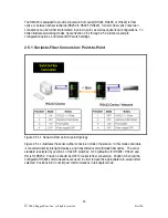
Figure 2.5.3  In serial conversion mode, one can convert from RS232 to RS485 / RS422 

 
Figure 2.5.3 illustrates the connections for conversion between RS232 and RS485 / 422 devices.  

In this mode of operation, RS232 voltage levels are converted to the appropriate RS485 or RS422 
signaling levels depending on the DIP switch configuration.  In this mode of operation position 2 of 

the DIPswitches must be in the ON position.  Figure 2.5.3 illustrates a RS232 device, connected to 
an RS485 device or network.  Since RS485 requires automatic turn-around, position 3 must be set 

to the OFF state, and position 6 – 8 of the DIP switches must reflect the proper operating baud 
rate. 

 
Note:    In this mode of operation, no isolation is provided between RS232 device and the 

RS485/422 network – both devices share the same common terminal.  It should be noted 
that the common terminal on RS232 devices are connected to ground.  In some instances 

(ie when connecting to large RS485 networks), it may be preferential for the user to leave 
the RS485/RS422 shield terminal unconnected to the RMC20 in this mode. 


15 

©


2006 RuggedCom Inc.  All rights reserved 


Rev100


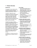
Summary of Contents for RuggedMC RMC20

Page 1: ...RuggedMC RMC20 Installation Guide RuggedCom Inc 30 Whitmore Road Woodbridge Ontario Canada L4L 7Z4 Web http www ruggedcom com Tel 905 856 5288 Fax 905 856 1995 Toll Free 888 264 0006...

Page 2: ...This product contains a laser system and is classified as a CLASS 1 LASER PRODUCT Caution Use of controls or adjustments or performance of procedures other than those specified herein may result in h...

Page 3: ...2 4 2 RS422 and RS485 Data Ports 11 2 5 RMC20 Configuration 13 2 5 1 Serial to Fiber Conversion Point to Point 14 2 5 2 Serial Standard Conversion 15 2 5 3 Serial to Fiber Conversion Loop Topology 16...

Page 4: ...rt PORT OPTIONS Protocol independent RS485 RS422 or RS232 user selectable conversion to multimode fiber optics ST connector only RS232 to RS485 RS422 conversion mode Fully EIA TIA RS485 RS422 RS232 co...

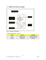
Page 5: ...ont Panel Detail The RMC20 LED definitions are as follows ITEM Activity Comments Tx LED Blinking Yellow Transmitting Serial Data RX LED Blinking Yellow Receiving Serial Data Power LED Solid Green Powe...

Page 6: ...1 2 RMC20 Side and Bottom View Fig 1 2 1 RMC20 Side and Bottom View 6 2006 RuggedCom Inc All rights reserved Rev100...

Page 7: ...2 Installation 2 1 DIN Rail Mounting Fig 2 1 1 RuggedMCTM DIN Rail Mounting 7 2006 RuggedCom Inc All rights reserved Rev100...

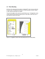
Page 8: ...unted using the optional panel mount adapter The panel mount adapter can be secured to a panel with three screws The RuggedMCTM product is easily mounted onto the panel mount adapter via the two metal...

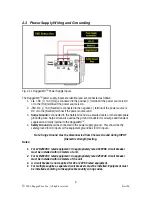
Page 9: ...ion circuitry internal to the RuggedMCTM 4 Safety Ground should be connected to the power supply ground This should be the safety ground for AC inputs or the equipment ground bus for DC inputs Note Su...

Page 10: ...minal block connections 2 4 1 RS232 Data Ports The RMC20 is equipped with a single EIA TIA RS232 compliant port consisting of three terminals Transmit Receive and Common The RS232 port is intended for...

Page 11: ...at ONE single point to avoid loop currents 6 The twisted pair should be terminated at each end of the chain Typically with a 120Ohm resistor and a 10nF capacitor in series across the twisted pair Bot...

Page 12: ...Fig 2 4 2 1 Conceptual RS485 wiring diagram 12 2006 RuggedCom Inc All rights reserved Rev100...

Page 13: ...osition DIP switch location for configuration RMC20 DIP Switch Configuration Settings Defined Position ON OFF 1 RS232 to fiber mode RS485 422 to fiber mode 2 RS232 to RS485 422 conversion mode Serial...

Page 14: ...Point Figure 2 5 1 1 Serial to Fiber point to point topology Figure 2 5 1 1 illustrates the serial to fiber conversion mode of operation In this mode serial data is converted directly into light impul...

Page 15: ...232 device connected to an RS485 device or network Since RS485 requires automatic turn around position 3 must be set to the OFF state and position 6 8 of the DIP switches must reflect the proper opera...

Page 16: ...This mode of operation requires that the master device tolerate receiving echoes of transmitted data since any transmissions will be received once again via the optical ring This topology can be used...

Page 17: ...lace only with same type and rating of fuse 3 2 Fiber Optical Port Specifications Parameter Specifications Mode Multimode Connector ST Typical Dist km 5 Optical Wavelength nm 820 Cable Size Core Cladd...

Page 18: ...fications Parameter Value Comments Dimensions 4 30 x 2 40 x 3 30 inches 110 x 61 x 84 mm Length x Width x Height Weight 1 5 lb 0 68 Kg Enclosure 18 gauge Galvanized Steel 18 2006 RuggedCom Inc All rig...

Page 19: ...4 kV 2 kV IEC 61000 4 5 Level 4 IEC Fast Transient 2 kV 1 kV IEC 61000 4 4 Level 4 ANSI IEEE Fast Transient 4 kV ANSI IEEE C37 90 1 IEC Radiated RFI Immunity 10 V m IEC 61000 4 3 ANSI IEEE Radiated R...

Page 20: ...Approved FCC FCC Part 15 Class A Approved CISPR EN55022 Class A Approved FDA CDRH 21 CFR Chapter 1 Subchapter J Compliant IEC EN EN60825 1 1994 A11 1996 A2 2001 Compliant 5 Warranty RuggedCom warrant...

Reviews: