5
VLBG-PLUS
WARNING
Observe the requested torque value before
each lifting or turning operation.
3.3.3 Forbidden lifting and turning operations
The following operations are forbidden:
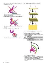
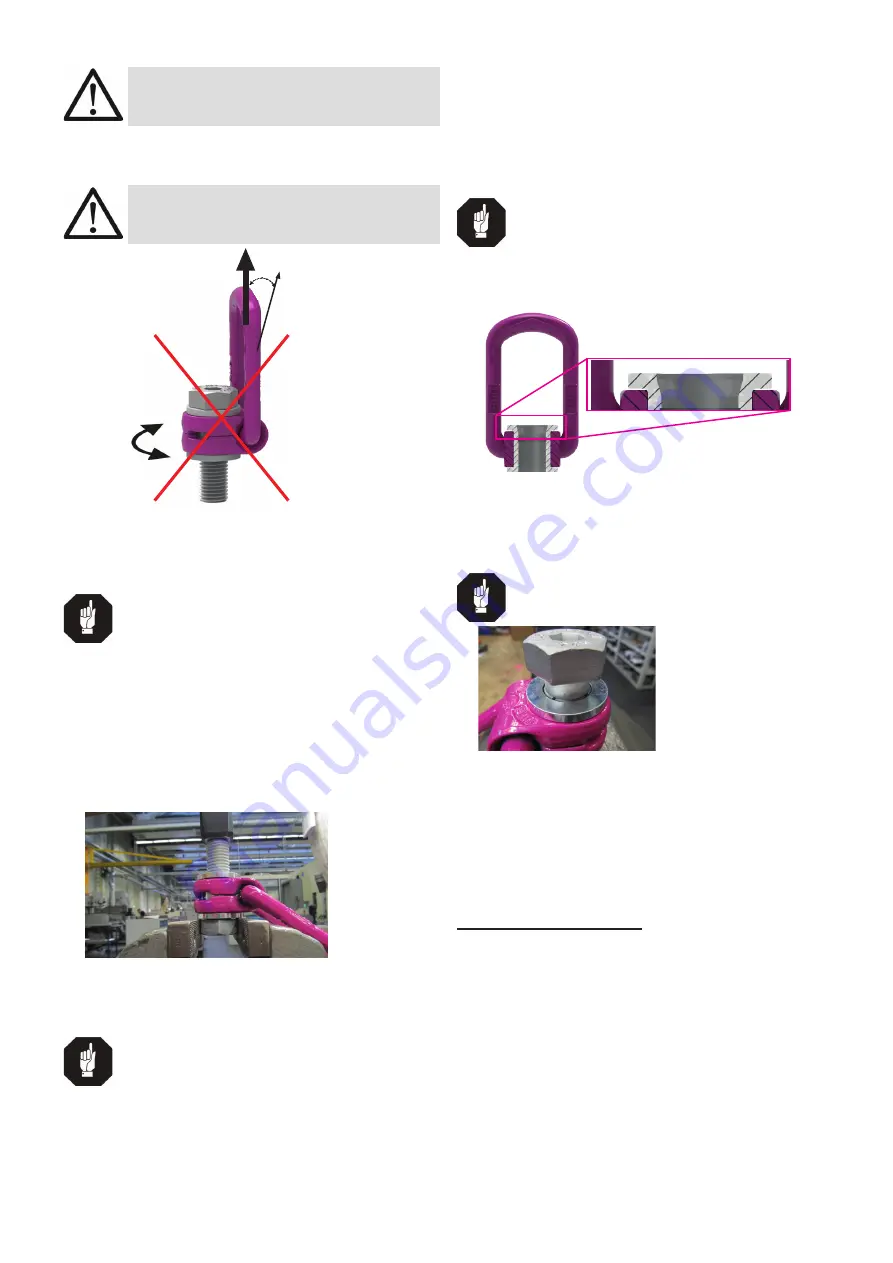
WARNING
The turning of the VLBG-PLUS under load in
the direction of the bolt axle (+15°) is forbidden.
F
15°
Pic. 7: Forbidden turning direction at loading in the
direction of the axle.
3.4 Dismantling / Assembling the RUD bolt
HINT
The dismantling / assembling and/or the ex-
change of the RUD bolt must only be executed
by a competent person!
3.4.1 Dismantling the bolt of the
VLBG-PLUS M8-M48
1. Position VLBG-PLUS with the thread end upwards
at the bushing on the top of the bench vice without
clamping the hexagon head of the bolt.
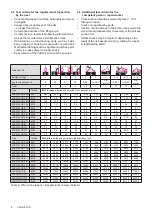
2. Slightly hit the bolt from the top to drive it out from the
bushing (Pic. 8).
Pic. 8: Dismantling position of the VLBG-PLUS
3.4.2 Assembling the bolt of the
VLBG-PLUS M8-M10
HINT
Only the appropriate strength class of bolt for
each specific size must be used!
M8-M10: ICE-Bolt only!
1. Insert the bolt into the drill hole in the socket until the
retaining ring is positioned on the socket
2. Squeeze the retaining ring together with flat pliers so
that it sits deeply in the groove of the nut.
3. Now insert the bolt with light hits with a hammer fully
into the socket.
4. Finally, control the tightness of the bolt. The bolt must
be easily rotatable by 360°.
3.4.3 Assembling the bolt for
VLBG-PLUS M12-M48
HINT
Only the stated strength of class for the respec-
tive size of the bolts must be used!
M12-M24: ICE-Bolt | M27-M48: 10.9
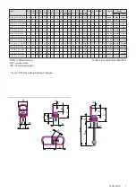
1. Insert the bolt into the bushing at the tapered end,
where the chamfer is (refer to Pic. 9).
Pic. 9: VLBG-PLUS in sectional view.
The insertion chamfer is visible on top of the bushing
2. Insert the bolt into the socket in such a way that the
retaining ring is circumferential deepened in the socket
and seated (refer to Pic. 10).
TIP
Turn the bolt a few times under slight pressure
so that it is centered in the retaining ring!
Pic. 10: Retaining ring positioned as circumferential in the
recess
3. Use a light tap on the head of the bolt so that the bolt
can be assembled up to the end stop of the bolt head
on the socket.
4. Finally, control the tightness and seating of the bolt.
The bolt must be easily rotatable by 360°.
4 Inspection / repair
4.1 Hints for periodical inspections
The operator must determine and specify the nature
and scope of the required tests as well as the periods
of repeating tests by means of a risk assessment (see
sections 4.2 and 4.3).
The continuing suitability of the anchor point must be
checked at least 1x year by an expert.
Depending on the usage conditions, f.e. frequent usage,
increased wear or corrosion, it might be necessary to
check in shorter periods than one year. The inspection has
also to be carried out after accidents and special incidents.


