4
ICE-LBG-SR
• RUD components are designed according to DIN
EN 818 and DIN EN 1677 for a dynamic load of
20,000 load cycles.
• Keep in mind that several load cycles can occur
with a lifting procedure
• Keep in mind that, due to the high dynamic
stress with high numbers of load cycles, that
there is a danger that the product will be da-
maged
• The BG/DGUV recommends: For higher dyna-
mic loading with a high number of load cycles
(continuous operation), the working load stress
must be reduced according to the driving mecha-
nism group 1Bm (M3 in accordance with DIN EN
818-7). Use a lifting point with a higher working
load limit.
• When attaching and removing the lifting means
(e.g. lifting chains), crushing, shearing, trapping and
impact spots must be prevented.
• Prevent damage being caused to the lifting means
by loading at sharp edged.
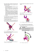
• Set the suspension ring of the ICE-LBG-SR in the
direction of force before attaching the lifting means.
F
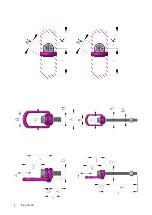
Pic. 1: Forbidden loading direction
• Keep in mind that the lifting means in the ICE-LBG-
SR must be freely movable.
Pic. 2: Use only suitable lifting means for hanging or
hooking into the ICE-LBG-SR
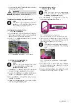
• A bending load of the suspension ring is not per-
mitted!
Pic. 3: The load must move freely and must not be
loaded at edges
• Always completely engage the lifting point.
Pic. 4: The lifting point must be completely screwed in.
3.3.2 Allowed lifting and turning operations
• Turning operations where the load ring will be tur-
ned into the load direction.
WARNING
The load ring must not support itself at
edges or other attachments.
Also the attached lifting mean must not
touch the head of the bolt.
F
Pic. 5: Pivoting in load direction
Summary of Contents for SuperRotation ICE-LBG-SR
Page 8: ...8 ICE LBG SR...

