Copyright © 2017 Ruckus Wireless, Inc.
Published July 2017, Part Number 800-71267-001 Rev C
Page 3 of 4
S
TEP
1
A
: C
ONNECTING
THE
SFP O
PTIC
M
ODULE
TO
THE
F
IBER
P
ORT
To connect to fiber backhaul, plug an SFP Optic module into the Fiber port. The SFP
module is hot-swappable and can be removed with fingers or simple tools.
NOTE
:
Recommended modules specified to work with this system are: Finisar GPON
FTGN2117P2TUN, Finisar EPON FTEN2217P1CUN-BC, Finisar 1000BaseLX
FTLF1318P3BTL, Xavi XO-3901 GPON ONT.
NOTE
:
The fiber cable must be a single diameter cable, not a zipcord.
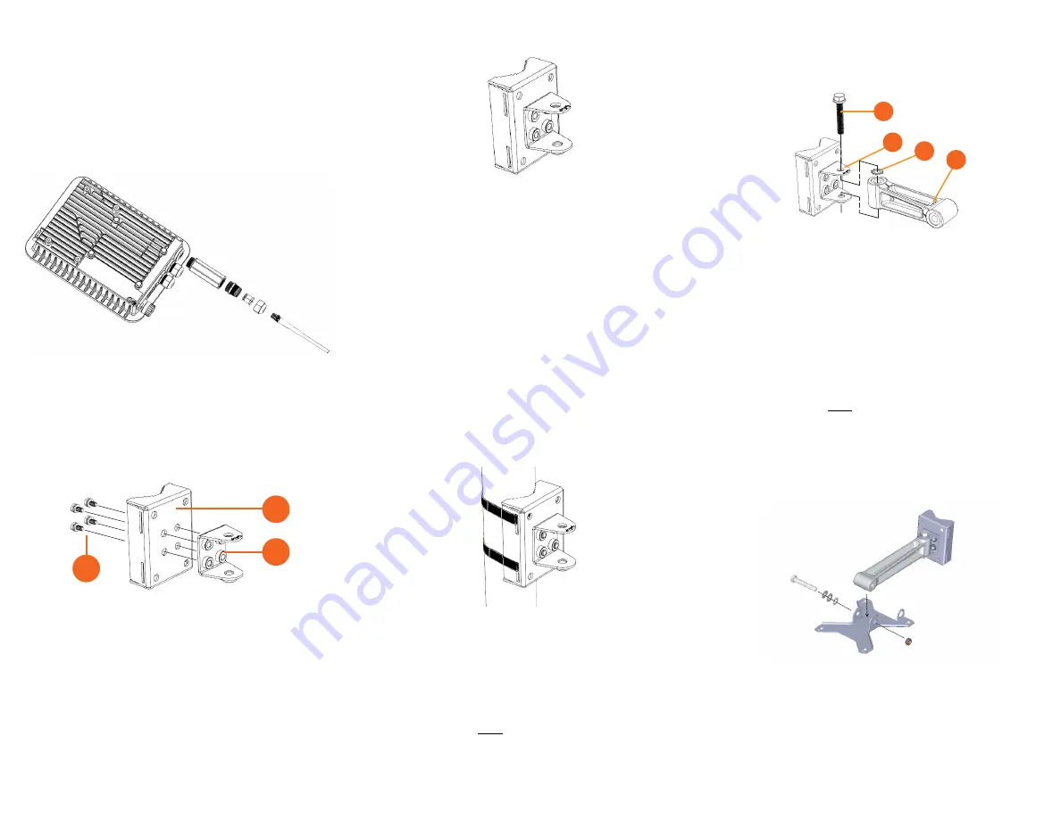
Figure 4:
SFP module cable gland assembly
S
TEP
2: A
TTACHING
THE
U-J
OINT
B
RACKET
TO
THE
M
OUNTING
B
RACKET
1
Position the U-joint bracket on the mounting bracket.
NOTE:
Mount the U-joint bracket in any direction on the mounting bracket,
preferably to allow AP azimuth adjustments. Then the AP bracket allows
AP elevation adjustments.
Figure 5:
U-joint bracket attached horizontally to the mounting bracket
2
Use four 1/4-28 bolt and washer sets (A) to mount the U-joint bracket (B) to the
mounting bracket (C). Tighten the bolts to 9.5 N.m (7 ft-lbs).
3
Step 3a: Attaching the Mounting Bracket to a Flat Surface
or
Step 3b: Attaching the Mounting Bracket to a Metal Pole
.
S
TEP
3
A
: A
TTACHING
THE
M
OUNTING
B
RACKET
TO
A
F
LAT
S
URFACE
1
Place the mounting bracket at the location on the flat surface where you want to
mount the AP. Use the holes on the mounting bracket as a template to mark the
locations of the mounting holes.
Figure 6:
Mounting bracket flat surface holes
2
Remove the mounting bracket from the flat surface.
3
Drill holes required for the mounting hardware.
NOTE:
The hardware required for mounting to a wall are not included in the mounting kit.
4
Attach the mounting bracket to the flat surface using the mounting hardware.
5
Using the mounting hardware instructions, tighten the hardware to secure the
mounting bracket.
6
Continue with
Step 4: Mounting the Linkage Bracket to the U-Joint Bracket
S
TEP
3
B
: A
TTACHING
THE
M
OUNTING
B
RACKET
TO
A
M
ETAL
P
OLE
1
Insert the open end of one steel clamp into the upper two slots on the mounting
bracket.
2
Take the other steel clamp and insert it into the lower two slots on the mounting
bracket.
NOTE:
The clamps can be daisy-chained together to accommodate larger
poles.
3
Use the clamps to attach the mounting bracket to the pole. Tighten the clamps to
3 N.m or 27 in-lbs, or per manufacturer’s specifications.
Figure 7:
Attaching the mounting bracket to a vertical pole
4
Continue with
Step 4: Mounting the Linkage Bracket to the U-Joint Bracket
S
TEP
4: M
OUNTING
THE
L
INKAGE
B
RACKET
TO
THE
U-J
OINT
B
RACKET
The linkage bracket attaches to the U-joint bracket using an M8 bolt and washer set. The
linkage bracket is symmetrical, and either end can be attached to the U-joint bracket.
NOTE:
Make sure that linkage bracket is installed with its serrated external-
tooth lock washer on the inside of the U-joint bracket flanges. This ensures
that the azimuth adjustment does not change.
1
Loosely assemble the linkage bracket (A), the U-joint bracket (C), one
serrated
external-tooth lock washer (B),
and one M8 bolt and washer set (D).
Figure 8:
Attaching the linkage bracket to the U-joint bracket
2
Set the azimuth required by the AP.
3
Tighten the M8 bolt to 13.6 N-m (10 ft-lbs).
4
Continue with
Step 5: Attach the AP bracket to the linkage bracket
.
S
TEP
5: A
TTACH
THE
AP
BRACKET
TO
THE
LINKAGE
BRACKET
Attach the AP bracket to the linkage bracket using the included bolt, nut, lock washer, flat
washer, serrated external-tooth washer shown in Figure 9.
The AP bracket attaches to the linkage bracket using an M8 bolt and washer set. The
linkage bracket is symmetrical, and either end can be attached to the AP bracket.
NOTE:
Make sure that linkage bracket is installed with its serrated external-
tooth lock washer on the inside of the AP bracket flanges. This ensures that
the elevation adjustment does not change.
1
As described in Step 4: Mounting the Linkage Bracket to the U-Joint Bracket, loosely
assemble the AP bracket (shown in Figure 10), the linkage bracket (A in Figure 8), the
second serrated external-tooth lock washer (B in Figure 8), and the second M8 bolt
and washer set (D in Figure 8).
Figure 9:
Attach the linkage bracket to the AP bracket
S
TEP
6: A
TTACHING
THE
AP B
RACKET
TO
THE
A
CCESS
P
OINT
1
Place the AP bracket onto the back side of the AP so that the four larger screw holes
on the bracket align with the four screw holes on the AP. Make sure that the end of
the AP bracket with the hoisting loop is on the same side as the AP
PoE IN
port.
C
B
A
A
C
B
D