background image

Accessories

20

Accessories

NOTE:

AZedit sessions are only enabled on J9 or J10 when the advanced communication boxes are enabled from 

“communications” screen and the correct baud rates are configured.

XCP-ADAM-MC Master Controller Breakout Panel

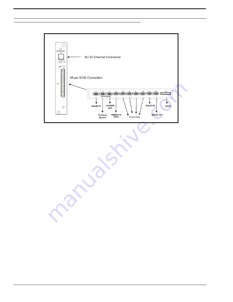
The XCP-ADAM-MC Breakout Panel allows many different peripherals to be connected to the master controller of an ADAM 
Intercom System, such as AZedit, trunking systems, UIOs, PAPs, LCPs, GPI/Os, etc. For the breakout panel pinouts, see pages 
9-15.

AZedit

AZedit is a Windows

®

-based, full-featured configuration software, providing online and offline configuration capabilities. It 

gives you the ability to manage multiple intercom systems, assign and reassign users to different ports, as well as dynamically 
add hardware to your system setup without jumper changes, rewiring, or taking the system offline. AZedit has the capability to 
load pre-set configuration files, which means configurations saved to a disk can be uploaded to the “live” application at 
anytime, without interruption.

The XCP-ADAM-MC breakout panel has three DB-9 connectors that can be used to connect to AZedit (AZedit #1, #2, and 
#3).

Trunking Systems

The RTS™ Trunking System manages intercommunications between separate intercom systems using intercom ports that 
have been reserved and interconnected between the intercom systems with devices in other frames. Keypanels or other data 
devices can then communicate with devices in other frames.

UIO-256

Each UIO-256 provides 16 GPI inputs and16 GPI outputs. The GPI inputs can be used just like keypanel keys to activate 
intercom ports, party lines, relays, etc. Each relay output provides a choice of normal open and normal closed contacts. The 

figure 6. 

Connection Diagram. The 68-pin SCSI can be attached to the

XCP-ADAM-MC.

Summary of Contents for MCII-e

Page 1: ...MCII e System Controller Card User Manual 9350 7734 000 Rev B April 2007 ...

Page 2: ...description of the problem and the serial number s SHIPPING TO THE MANUFACTURER All shipments of product should be made via UPS Ground prepaid you may request from Factory Service a different shipment method Any shipment upgrades will be paid by the customer The equipment should be shipped in the original packing carton If the original carton is not available use any suitable container that is rig...

Page 3: ...equirements 14 Ethernet Setup for MCII e System Controller 14 Set the IP Address for the MCII e System Controller 14 Download Firmware for the MCII e System Controller 16 Accessories 19 Accessories 20 XCP ADAM MC Master Controller Breakout Panel 20 AZedit 20 Trunking Systems 20 UIO 256 20 PAP 21 LCP 21 GPI O General Purpose Input Output 21 Trunking and the MCII e System 23 Trunking and the MCII e ...

Page 4: ......

Page 5: ...3 CHAPTER 1 Introduction In this chapter Introduction Features Specifications Reference View Front Card Reference View Back Card DIP Switches Connector Pin outs ...

Page 6: ...m Controller card is only for use in the ADAM Matrix Intercom System and cannot be intermixed with older ADAM master controllers in a given frame Features Installation The MCII e System Controller card is hot swappable and installs into slots 19 or 20 in an ADAM Intercom System Trunk Capable The MCII e System Controller card supports ancillary data control for use with Telex Intelligent Trunking E...

Page 7: ...5 System Diagram 32 MB of SDRAM 8Mbytes Configuration Flash System Diagram Figure 1 System Diagram MCII e Master Controller MCII e AZedit ADAM MCII e ADAM LAN MCII e MCII e ...

Page 8: ... BANK J500 AND J501 RS 232 OR RS 485 FOR J1 AND J2 SERIAL PORTS J100 DEBUG SERIAL PORT J500 Azedit 1 J1 J501 Trunking J2 RS 232 1 2 default 2 3 RS 485 2 3 1 2 default SE01 FOR INTERNAL USE ONLY ALL DIP SWITCHES MUST BE IN OFF POSITION Jumper Settings For Programming Use ONLY J801 Pins 1 2 must be shorted Pins 3 4 must be shorted ...

Page 9: ...ot 3 is alive and talking 9 I O Card in Slot 2 is alive and talking 8 I O Card in Slot 1 is alive and talking NOTE There is no LED for I O card in slot 17 ON if acting as the active controller OFF if acting as standby Flashes while transmitting data on control bus to another card Flashes while receiving data on control bus from another card Flashes while transmitting data on private bus to active ...

Page 10: ... set in AZedit must match the baud rate setting of the Master Controllers in ADAM DEFAULT OPEN OPEN 9600 CLOSED 38 4k Baud DIP Switches 3 4 and 5 Reserved keep in OPEN position DIP Switch 6 Debug Only Must be in OPEN position DIP Switch 7 Determines Master Slave Frame in a multi frame system Figure 4 Back Card Figure 5 Dip Switch SE02 ETHERNET J1 J2 LINK ACT RJ 45 Ethernet Connection 68 pin SCSI C...

Page 11: ... OPEN Slave Frame CLOSED Master Frame DIP Switch 8 Debug Only Must be in OPEN position Warning DIP Switches 1 6 and 8 should always be left in the OPEN position These are reserved for debugging and can have unintended consequences ...

Page 12: ...5 TX RX 36 2 Ground 6 3 RS232C RX 4 Not Used 41 5 RS422 TX 39 6 RS485 TX RX 36 7 Ground 40 8 RS232C TX 7 9 RS422 TX UIO 256 PAP LCP 68 pin Master Controller J 3 of XCP ADAM MC Assignment 2W 8 1 RS485 TX RX 9 2 Ground 3 Not Used 4 Not Used 44 5 RS422 TX 42 6 RS485 TX RX 9 7 Ground 8 Not Used 10 9 RS422 TX General Purpose 68 pin Master Controller J 4 of XCP ADAM MC Assignment 2W 11 1 RS485 TX RX 43 ...

Page 13: ...RS485 TX RX 48 2 Ground 3 Not Used 4 Not Used 5 Not Used 49 6 RS485 TX RX 48 7 Ground 8 Not Used 9 Not Used General Purpose Bus Exp 68 pin Master Controller J 7 of XCP ADAM MC Assignment 2W 16 1 RS485 TX RX 17 2 Ground 3 Not Used 4 Not Used 5 Not Used 50 6 RS485 TX RX 17 7 Ground 8 Not Used 9 Not Used General Purpose Bus Exp 68 pin Master Controller J 8 of XCP ADAM MC Assignment 2W 18 1 RS485 TX R...

Page 14: ...C Assignment Signal 22 1 MI 0 Logical Input 0 23 2 MI 1 Logical Input 1 24 3 MI 2 Logical Input 2 25 4 MI 3 Logical Input 3 26 5 MI 4 Logical Input 4 27 6 MI 5 Logical Input 5 28 7 MI 6 Logical Input 6 29 8 MI 7 Logical Input 7 30 9 Ground Ground 31 10 Ground Ground 32 11 Ground Ground 33 12 Ground Ground 34 13 Ground Ground 55 14 MO 0 Logical Output 0 56 15 MO 1 Logical Output 1 57 16 MO 2 Logica...

Page 15: ...13 CHAPTER 2 Configuring the MCII e In this chapter System Requirements Ethernet Setup for the MCII e System Controller Download Firmware for the MCII e System Controller ...

Page 16: ...TE The PC must be running version 2 08 01 or later of AZedit and have an Ethernet card installed The MCII e can support up to 32 concurrent sessions of AZedit on Ethernet Verify the MCII e is connected to the PC using a RS232 ADAM standard cable Connect J1 on the XCP ADAM MC to the COM port on the PC NOTE For more information on Network Basics see the Basic Networking Guide found at our website ht...

Page 17: ...the same on both the active and standby MC II e System Controller Cards The same screen you use to set the network settings can be used to view the settings as well You must be connected using a serial connection via J1 to make changes but you can view them with any type of AZedit connection J1 J9 J10 or Ethernet 6 Click Apply 7 Click Close The Ethernet Setup window is closed 8 Connect the MCII e ...

Page 18: ...CII e System Controller Download Firmware for the MCII e System Controller WARNING The following procedure will cause one or more brief disruptions in intercom communications Also SAVE your intercom system configuration From the File menu select SAVE Later if you need to restore the intercom configuration from disk use Send File in the Online Menu Before you begin be sure to verify that SERVER mod...

Page 19: ...re is any disruption in the communications link during the download you will get an error message In this case repeat the download 7 When the file has been completely downloaded the MCII e System Controller will begin processing the update IMPORTANT Any disruption at this point such as loss of power removing or resetting cards may result in Master Controller failure If this happens you will have t...

Page 20: ...Configuring the MCII e 18 ...

Page 21: ...19 CHAPTER 3 Accessories In this chapter Accessories AZedit UIO 256 PAP LCP General Purpose ...

Page 22: ...ut jumper changes rewiring or taking the system offline AZedit has the capability to load pre set configuration files which means configurations saved to a disk can be uploaded to the live application at anytime without interruption The XCP ADAM MC breakout panel has three DB 9 connectors that can be used to connect to AZedit AZedit 1 2 and 3 Trunking Systems The RTS Trunking System manages interc...

Page 23: ...he LCP allows you to adjust analog input and output gains assign sources to IFB outputs and make changes on the fly and to add members to a party line on the fly GPI O General Purpose Input Output J11 provides 8 general purpose control inputs and 8 general purpose control outputs The control inputs can be used just like keypanel keys to activate intercom ports party lines relays etc The control ou...

Page 24: ...Accessories 22 ...

Page 25: ...ng and the MCII e System In this chapter Enable Trunk Support for MCII e System Controller Card Connect MCII e to the Trunk Master Data Configure TrunkEdit and AZedit to Communicate with the MCII e System Controller Card ...

Page 26: ...s option the baud rate is changed to 9600 baud instead of the default 38 4K To enable the Remote Trunk Master do the following WARNING Enabling this option will cause the system to reset All data will be erased in the frame Be sure to save your system setup to disk before performing this task 1 Remove the Standby Master Contoller 2 From the AZedit main menu select Options The Options sub menu appe...

Page 27: ...ield 5 Select the Baud Rate field and enter the baud rate to match the baud setting of the Intercom Trunking port 38 4K or 9600 6 When you are finished click the Send button to send the changes to the Trunk Master When the changes are sent to the Trunk Master the MCII e connects to the Trunk Master and uploads the remote ports Once the MCII e has uploaded this data it sends its port alphas to the ...

Page 28: ...e trunk connection i e ADAM 4 In the Port Field enter the port number where ICOM1 is assigned i e N014 Or in the Alpha field enter the Alpha of the ICOM1 system i e N014 5 In the ICOM2 field enter the name of the system ICOM1 is linked to i e INT1 6 In the Port field enter the port number where ICOM2 is assigned i e N005 Or in the Alpha field enter the alpha of the ICOM2 system 7 Once finished wit...

Reviews: