background image

LN1000 IS Annunciator 


27 

ISA – F2M-1 First-up with 

Manual Reset 


with no subsequent alarm flashing and silence pushbutton  


PROCESS

LCD

LED

SEQUENCE

LED

ON

FIRST ALARM

SEQUENCE ISA   F2M-1

(MANUAL RESET FIRST OUT WITH NO SUBSEQUENT ALARM FLASHING & SILENCED PUSHBUTTON)

AUDIBLE

ACKNOWLEDGE

LCD

SILENT

FLASHING

SILENCE

ACKNOWLEDGE 

WHILE ABNORMAL

ACKNOWLEDGED

AUDIBLE

LCD

LED

SEQUENCE

PROCESS

FLASHING

ABNORMAL

SILENCE OR ACKN

PROCESS

SEQUENCE

RESET WHILE

NORMAL

AUDIBLE

LCD

SEQUENCE

LED

SUBSEQUENT TO 

ABNORMAL

SUBSEQUENT

ALARM

SILENT

OFF

NORMAL

FIRST TO 

ABNORMAL

SEQUENCE DIAGRAM

OR NORMAL

ABNORMAL

OR NORMAL

ABNORMAL

OR NORMAL

NORMAL

PROCESS

N

AUDIBLE

AUDIBLE

(A)

F

N

PROCESS

ABNORMAL

OR NORMAL

SEQEUNCE

FIRST SILENCED

LED

(A)

F

N

LCD

A

N

SILENT

AUDIBLE

N

A

AUDIBLE

ON

Summary of Contents for LN1000

Page 1: ...claration added KU TMcL 9 15 05 09 Fig 13 4 Corrected PC DA 10 26 05 09 Fig 6 1 6 2 13 3 Corrected PC DA 11 1 12 09 Baseefa notified body number added and declaration updated WF PH 12 24 04 12 D of C updated in line with current standards BC WF 13 06 09 2012 Date error in D of C corrected NG WF 14 12 11 2012 D of C updated in line with current standards WF PH 15 11 12 2012 Input connection drawing...

Page 2: ...patented feature It must not be reproduced in whole or in part or used for tendering or manufacturing purposes except under an agreement or with the consent in writing of RTK Instruments Ltd and then only on the condition that this notice is included in any such reproduction Information furnished is believed to be accurate but no liability in respect of any use of it is accepted by RTK Instruments...

Page 3: ...10 LN1000 AC ALARM CARD 10 LN1000 SC SEQUENCE CARD 10 SECTION 4 TECHNICAL SPECIFICATION 11 LOCATION 11 POWER REQUIREMENTS 11 TERMINALS 11 EMC COMPLIANCE 11 ENVIRONMENT 11 ENVIRONMENTAL PROTECTION 11 CONSTRUCTION 11 PANEL CUT OUT 11 WEIGHT 11 ALARM INPUTS 12 INHIBIT INPUTS 12 ALARM OUTPUTS 12 PROGRAMMABLE FEATURES 13 LN1000 SC SEQUENCE CARD 13 INPUT 13 OUTPUTS 13 PUSH BUTTONS 14 OTHER FEATURES 14 S...

Page 4: ... IDENTIFICATION LEGENDS 35 SECTION 9 FIELD WIRING 36 CERTIFICATION 36 GENERAL 36 SECTION 10 TERMINAL NUMBERS 38 SEQUENCE CARD TERMINAL NUMBERING 38 ALARM CARD TERMINAL NUMBERING 38 SECTION 11 SYSTEM SUPPLY CONNECTIONS 39 POWER SUPPLY 39 SECTION 12 SYSTEM INPUT CONNECTIONS 40 ALARM INPUTS HAZARDOUS AREAS 40 INHIBIT INPUTS 44 EXTERNAL PUSHBUTTON INPUTS 44 SECTION 13 SYSTEM OUTPUT CONNECTIONS 45 GENE...

Page 5: ...CK 57 DISPLAYS DO NOT OPERATE WHEN TEST PUSHBUTTON PRESSED CHECK 57 ALL ALARM CHANNELS FUNCTION INCORRECTLY CHECK 57 ONE CHANNEL FUNCTIONS INCORRECTLY CHECK 57 THE DIL SWITCH PROGRAMMING DOES NOT FUNCTION CHECK 57 THE AUDIBLE IS NOT WORKING CORRECTLY CHECK 57 THE IS RELAYS ARE NOT SWITCHING CORRECTLY CHECK 58 ROUTINE MAINTENANCE 58 RECOMMENDED SPARES 58 SECTION 17 APPENDIX A 59 CABLE PARAMETERS 59...

Page 6: ...t to drive up to 32 alarm channels The annunciator functions in a similar manner to a conventional safe area annunciator but because of the limited power available the information is displayed using a combination of high efficiency LED s and LCD s in the place of incandescent lamps The system is fully programmable via DIL switches for a range of commonly used functions and features The alarm seque...

Page 7: ... these are simply added to the chassis to make up the alarm system of the required size Complete System Figure 2 1 on the following page shows a typical system those parts shown shaded illustrate an alarm system in its simplest form All the complementary parts needed to design a more complex system are manufactured by RTK and can be supplied together with interconnection diagrams RTK Instruments w...

Page 8: ... and payload are critical factors especially offshore Group Outputs A number of outputs are available as standard to drive external audibles and control other parts of the plant in the advent of certain alarms occurring These outputs are programmable to operate in many different ways Inputs The alarm inputs are normally situated in the hazardous area but can also be connected to the LN1000 from th...

Page 9: ...y components Figure 2 1 DAE 149 DAD 149 PSU DA 161 BATTERY BACKUP REMOTE CONTROL PUSHBUTTONS DA135 LED BEACON DB 5 100dB SOUNDER TO OTHER I S EQUIPMENT ALARM INPUTS FROM SAFE AREA AC MAINS 24V DC LN1000 INTRINSICALLY SAFE ANNUNCIATOR BASIC SYSTEM SAFE AREA HAZARDOUS AREA ...

Page 10: ...tputs LN1000 AC Alarm Card The Alarm Card monitors two alarm channels and each channel has the following inputs and outputs ALARM INPUT CONNECTED TO THE VOLT FREE ALARM CONTACTS INHIBIT INPUTS Connected To Volt Free Contacts To Inhibit That Alarm Channel GROUP A OUTPUT Configurable To Follow The Alarm Logic Or The Field Contact GROUP B OUTPUT Configurable To Follow The Alarm Logic Or The Audible L...

Page 11: ...es mode 4kV Emissions To EN50081 1 1992 Environment Operating temperature 20 to 60 C Storage temperature 20 to 80 C Humidity 0 95 RH non condensing Environmental Protection Door to case IP65 Case to panel IP65 Rear of enclosure IP20 Construction Case Stainless Steel Front fascia High impact resistant polyurethane Membrane Polyester Panel Cut Out LN1000 12 8 or 12Way 121 x 270mm 0 5mm H x W LN1000 ...

Page 12: ... contact 5VDC typical Alarm Outputs Group Trip A Output GTA Configurable a Follows alarm logic b Follows field contact Group Trip B Output GTB Configurable a Follows alarm logic b Follows audible Group Trip Outputs A and B The above two outputs are configurable as energised or de energised on alarm a Low for normal b Low for alarm Option a or b must be the same for both GTA and GTB outputs of each...

Page 13: ...d contacts remain abnormal for greater than the delay time LN1000 SC Sequence Card Input Power Supplied from IS isolator sited in the safe area Outputs Ext Sound Low level DC signal follows audible on ISA sequence May be used for switching DAA149 or DAD149 IS relays B1 This output is configurable for both polarity and function The function can be of two types either following the alarm logic or th...

Page 14: ...rrespective of alarm status Will also drive the local horn and the external sounder This function operates as long as the pushbutton is pressed This function will not change the alarm state SYSTEM TEST S T Pressing and holding Silence and Test buttons for 4 seconds will cause the LN1000 to enter a test routine Each channel is put into the highest state of alarm and latched in it is then necessary ...

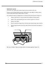
Page 15: ...a is removed by unfastening the retained screws and lifting the front panel down until it is held on the retaining straps Alarm Cards Each two channel alarm card is fitted with an LED and a Liquid Crystal Display LCD for each channel The LED follows the normal alarm sequence and the LCD indicates the sequence field contact status first up and inhibit state of the alarm channel To identify each ala...

Page 16: ...tor is mounted in a stainless steel enclosure with the terminals wired and loomed around the hinge to a row of 2 5mm terminals ready for external connection via the bottom gland plate Channel numbering The channels are numbered starting from the Sequence Card towards the left With two alarm channels on each card the lowest channel number is always the upper channel ...

Page 17: ... AS REQUIRED FOR FIELD CABLE GLANDS GROMMETS SERIAL NUMBER LABEL UNIT ASSEMBLED INTO PANEL FROM THE FRONT WITH PANEL MOUNTING BRACKETS AND CABLE HOUSING REMOVED RECOMMENDED PANEL THICKNESS STEEL 1 6 4 0mm 16 8SWG ALUMINIUM 2 0 4 0mm 14 8SWG 12 10 12 10 4 OFF TACTILE MEMBRANE SWITCHES 8 4 6 2 T 4 6 8 R 2 M4 CAPTIVATED SCREWS WITHIN FASCIA GASKET BETWEEN THE BOX AND THE FASCIA POSITIONED INSIDE FASC...

Page 18: ...4 2 3 1 20 18 3 1 S A 4 2 R T HIGH IMPACT POLYURETHANE FASCIA UNIT ASSEMBLED INTO PANEL FROM THE FRONT WITH PANEL MOUNTING BRACKETS AND CABLE HOUSING REMOVED ENVIRONMENT PROTECTION REAR IP20 PANEL MOUNTING BRACKETS ASSEMBLED IN FROM REAR ENSURING HOOK IS POSITIONED IN THE SLOT ENVIRONMENT PROTECTION FRONT IP65 CABLE HOUSING DRILL AS REQUIRED FOR FIELD CABLE GLANDS GROMMETS SERIAL NUMBER LABEL RECO...

Page 19: ...iator overall layout and dimensions Figure 6 3 480 0 240 0 SIDE VIEW 26 0 319 0 480 0 R A 11 11 12 12 170 0 9 9 5 7 7 5 10 10 6 8 8 6 SYSTEM 3 3 1 1 4 4 2 2 TEST INTERNAL VIEW FRONT VIEW S T BOTTOM CABLE ENTRY WITH PUNCHED HOLES THROUGH 2 x GLAND PLATES ...

Page 20: ... 25 0 100 0 INTERNAL VIEW 720 0 720 0 240 0 19 21 17 17 20 22 24 26 18 11 12 11 12 14 16 15 13 15 13 14 16 2 4 10 8 6 7 9 3 5 7 9 3 5 S 1 A 1 SYSTEM TEST 4 WITH PUNCHED HOLES 2 x GLAND PLATES BOTTOM CABLE ENTRY 298 0 384 0 28 27 27 28 30 32 31 29 31 29 30 32 18 20 22 24 26 23 25 19 21 23 25 ...

Page 21: ... important to know which of them was the first to occur This is achieved by both flashing the first up alarm in a different manner compared to the subsequent alarms and also showing the F in the LCD display Three different first up sequences are available F1 F2 and F3 as detailed below and in the following sequence tables First up operation should be used with care with the auto reset sequence as ...

Page 22: ...immediately on Acknowledge Ringback sequence This mode is used to indicate to operators that the alarm contact has returned back to its normal state hence avoiding having to continually press the reset pushbutton to see if the plant contacts have returned to their non alarm state TO CHANGE FROM ONE SEQUENCE TO ANOTHER SEE THE DIL SWITCH SETTINGS DETAILS IN THE SECTION 14 SYSTEM CONFIGURATION AND P...

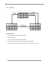
Page 23: ...ew settings The following tables show the most commonly used examples ISA M Manual Reset PROCESS SEQUENCE LED LCD ABNORMAL OR NORMAL ALARM FLASHING A SEQUENCE PROCESS OFF LED LCD N NORMAL NORMAL ACKNOWLEDGE RESET WHILE NORMAL TO ABNORMAL LCD LED SEQUENCE PROCESS ABNORMAL OR NORMAL ON ACKNOW AUDIBLE SILENT AUDIBLE AUDIBLE N AUDIBLE SILENT A N Sequence features Acknowledge reset and lamp test pushbu...

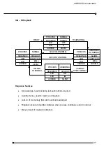
Page 24: ... NORMAL LCD LED SEQUENCE PROCESS ABNORMAL OR NORMAL ON ACKNOW AUDIBLE SILENT AUDIBLE AUDIBLE N AUDIBLE SILENT N A A Sequence features Acknowledge and lamp test pushbuttons required Alarm audible device Lock in of momentary alarms until acknowledged The audible device is silenced and flashing stops when acknowledged Automatic reset of acknowledged alarms when process conditions return to normal ...

Page 25: ...BACK RETURN TO NORMAL TO ABNORMAL RESET RETURN TO NORMAL ACKNOW WHILE NORMAL AUDIBLE SILENT AUDIBLE AUDIBLE N SILENT AUDIBLE AUDIBLE A N ACK WHILE NORMAL SILENT Sequence features Acknowledge reset and lamp test pushbuttons required Audible device used for alarm and ringback Lock in of momentary first alarm until acknowledged Ringback visual and audible indicates when process conditions return to n...

Page 26: ... A F N AUDIBLE SILENT LED LCD A ON ACKNOWLEDGE WHILE NORMAL first up reset Sequence features Acknowledge and lamp test pushbuttons required Alarm audible device Lock in of momentary first alarm until acknowledged No lock in of momentary subsequent alarms Flashing and audible indications for first alarm only New subsequent alarms go to the acknowledged state First up indication is reset and the aud...

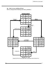
Page 27: ...GE LCD SILENT FLASHING SILENCE ACKNOWLEDGE WHILE ABNORMAL ACKNOWLEDGED AUDIBLE LCD LED SEQUENCE PROCESS FLASHING ABNORMAL SILENCE OR ACKN PROCESS SEQUENCE RESET WHILE NORMAL AUDIBLE LCD SEQUENCE LED SUBSEQUENT TO ABNORMAL SUBSEQUENT ALARM SILENT OFF NORMAL FIRST TO ABNORMAL SEQUENCE DIAGRAM OR NORMAL ABNORMAL OR NORMAL ABNORMAL OR NORMAL NORMAL PROCESS N AUDIBLE AUDIBLE A F N PROCESS ABNORMAL OR N...

Page 28: ...lence pushbutton to silence the audible device while retaining first up flashing indication Flashing indication for first alarm only New subsequent alarms have the same visual as acknowledged alarms First up indication is reset and the audible devices silenced when acknowledged Manual reset of acknowledged alarms after process conditions return to normal ...

Page 29: ...ERMITTENT FLASHING FIRST ALARM SUBSEQUENT ACKNOWLEDGE ON ABNORMAL LED LCD PROCESS STATE SEQUENCE LED PROCESS ON SUBSEQUENT ALARM ABNORMAL SEQUENCE DIAGRAM RETURN TO NORMAL ACKNOWLEDGE WHILE NORMAL AUDIBLE LED SEQUENCE FIRST TO ABNORMAL SUBSEQUENT TO ABNORMAL SILENT OFF NORMAL ABNORMAL ACKOWLEDGED OR NORMAL OR NORMAL OR NORMAL PROCESS NORMAL LCD N AUDIBLE AUDIBLE A N AUDIBLE AUDIBLE A N F AUDIBLE S...

Page 30: ...ice Lock in of momentary first alarm until acknowledged First up flashing different from subsequent flashing First up reset pushbutton to change the first up visual indication to be the same as subsequent visual indication Automatic reset of acknowledged alarms when process conditions return to normal ...

Page 31: ...e cable housing to suit glands grommets to be used and re fit onto box 7 Wire as required 8 Re fit the rear cover Removal fitting of Fascia Panel Antistatic precautions should be taken when the fascia is removed and when handling Sequence Alarm Cards see Appendix B for details Removal 1 Use the special socket provided for fastening unfastening the fascia screws 2 Loosen fascia screws evenly until ...

Page 32: ...scia straps and Pushbutton Board ribbon cable do not trap between fascia and box seal 2 Hold fascia in position while partly tightening fascia screws 3 Tighten fascia screws evenly to seal to the enclosure some resistance will be felt due to the compression of the seal gasket do not over tighten ...

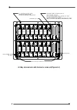
Page 33: ...irmly located in the two connectors mounted on the backplane 12 Way Annunciator with the fascia removed Figure 8 1 SEQUENCE CARD FRONT FASCIA LOCATION HOLES 5v ALARM 5 ALARM 6 ALARM 4 ALARM 3 ALARM 2 ALARM 1 ALARM CARDS 6 MAX BOX CABLE HOUSING REAR COVER AND PANEL MOUNTING BRACKETS ALL MANUFACTURED FROM STAINLESS STEEL FASCIA RETAINING STRAPS IN 2 PLACES METHOD FOR ADDING OR REMOVAL OF CARDS 1 REM...

Page 34: ... ALARM 11 ALARM 10 ALARM 19 METHOD FOR ADDING OR REMOVAL OF CARDS 1 REMOVE POWER FROM UNIT 2 HOLD STRAPS ON EITHER SIDE OF CARDS AND PULL FIRMLY 3 FITMENT IS THE REVERSAL OF ABOVE 4 ENSURE CARDS ARE FULLY INSERTED BEFORE REFITTING FASCIA 5 ANTI STATIC PRECAUTIONS MUST BE UNDERTAKEN AT ALL TIMES BOX CABLE HOUSING REAR COVER AND PANEL MOUNTING BRACKETS ALL MANUFACTURED FROM STAINLESS STEEL FASCIA RE...

Page 35: ...ged by the user Refer to the actions below and Figure 8 3 1 Remove fascia from the unit see section Removal fitting of Fascia panel 2 Remove the Legend Retaining bar from behind the legend to be removed 3 Remove the Legend 4 Place the replacement legend into the fascia with machined edges top and bottom 5 Slide the legend retaining bar into the slots positioned either side of the legend to secure ...

Page 36: ...he edge connector for each card All wiring must meet the Cable Parameter requirements detailed in Appendix A The terminals are clearly marked on the backplane as to their function i e AL1 AL2 etc for the Alarm Cards and Sequence Card are marked as such The individual terminals for each block are numbered 1 to 12 The terminal connectors are clipped into the backplane These should not be removed fro...

Page 37: ...UNTING BRACKETS M4 CHASSIS EARTH STUD TERMINATIONS BOTH SIDES TOP BACKPLANE ASSEMBLY BOTTOM BACKPLANE ASSEMBLY S E Q U E N C E C A R D F E C CA R D A L 1 1 12 12 1 A L 2 A L 3 A L 4 A L 5 A L 6 1 12 1 1 1 1 1 12 12 12 12 12 J8 1 J7 J6 J5 J4 J3 J2 J1 1 1 1 1 1 1 1 A L 7 1 12 J9 1 A L 8 1 12 J10 1 S E Q U E N C E C A R D F E C C A R D A L 1 1 12 12 1 A L 2 A L 3 A L 4 A L 5 A L 6 1 12 1 1 1 1 1 12 1...

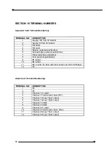
Page 38: ... Test external pushbutton 9 B1 output 10 B2 output 11 Ext sound To drive external sounder via DA 149 Relays 12 5V Alarm Card Terminal Numbering TERMINAL NO DESCRIPTION 1 5V 2 0V 3 Channel 1 H output 4 Channel 1 Field contact input FC1 5 Channel 1 Group Trip A output 6 Channel 1 Group Trip B output 7 Channel 1 Inhibit 8 Channel 2 Inhibit 9 Channel 2 H output 10 Channel 2 Field contact input FC2 11 ...

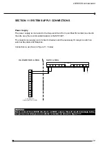
Page 39: ...channels and the necessary IS relays to switch on external Sounders and Beacons Connection is as shown in Figure 11 1 below IS power supply connection Figure 11 1 WARNING Never connect the LN1000 directly to a 24VDC supply this will result in damage to the sequence card Always use a suitable is isolator as shown in figure 11 1 12 11 10 9 8 7 6 5 4 3 2 1 S E Q U E N C E C A R D H A Z A R D O U S A ...

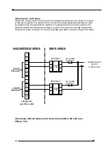
Page 40: ...gnals of 5VDC and 250uA Each contact should be wired as a conductor pair using either two core or suitable multi pair screened cable Cable parameters are listed in Appendix A Usually normally closed open to alarm contacts are used and these are wired as shown in Figure 12 1 If normally open close to alarm contacts are used the terminal connections are as shown in Figure 12 2 Alarm ways wired with ...

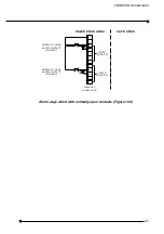
Page 41: ...arm ways wired with normally open contacts Figure 12 2 12 11 10 9 8 7 6 5 4 3 2 1 LN1000 AC ALARM CARD UPPER WINDOW HAZARDOUS AREA SAFE AREA LOWER WINDOW ALARM CONTACT CHANNEL 1 ALARM CONTACT CHANNEL 2 NORMALLY OPEN NORMALLY OPEN ...

Page 42: ...ose is the DAE149 or DAD149 Intrinsically Safe Relay Typical connections for normally closed alarm contacts are shown in Figure 12 3 and for normally open alarm contacts in Figure 12 4 below Alarm ways with normally closed contacts mounted in the safe area Figure 12 3 12 11 10 9 8 7 6 5 4 3 2 1 LN1000 AC ALARM CARD UPPER WINDOW HAZARDOUS AREA SAFE AREA LOWER WINDOW IS RELAY 2 1 4 3 DAE 149 IS RELA...

Page 43: ...en using the DA 149 is relays ensure the polarity is correct for both the coil and contact connections 12 11 10 9 8 7 6 5 4 3 2 1 LN1000 AC ALARMCARD UPPER WINDOW HAZARDOUSAREA SAFEAREA LOWER WINDOW ISRELAY 2 1 4 3 DAE 149 ISRELAY 2 1 4 3 DAE 149 N OALARM CONTACT N OALARM CONTACT ALARMCONTACT SUPPLY 10 250VAC DC ...

Page 44: ...ted to the Sequence Card terminals for remote use Good quality pushbuttons should be used with contacts suitable for 5VDC with a low current capability of 0 1mA They must meet the requirements defined for simple apparatus in Clause 5 4 of BS EN50020 They should be separated from other electrical equipment and isolated from earth If these requirements cannot be met the signals must be isolated by t...

Page 45: ...signated Horn and Ext Sound The Horn output is not used If a higher level of sound is required the Ext Sound output is used to drive an external IS relay which is used to switch power to a high output sounder e g Type DB5 or DB7 These examples are shown in Figures 13 1 and 13 2 This output follows the alarm sequence as defined in section 6 on Alarm Sequences When the Test pushbutton is pressed bot...

Page 46: ...onfiguration is shown in Figure 13 3 Connections to sounder using hazardous area mounted IS relay Figure 13 2 WARNING When using the DA 149 is relays ensure the polarity is correct for both the coil and contact connections LN1000 SC SEQUENCE CARD 12 11 8 9 10 7 DAD 149 3 4 1 2 IS RELAY SAFE AREA HAZARDOUS AREA DB 5 100dB IS SOUNDER 1 2 11 12 MTL5021 ...

Page 47: ...lternatively active if any field contact in Field Contact Group is abnormal The operational mode is user selectable by DIL switch The output is active low or active high again selectable by DIL switch B2 output The B2 output pulses for 1 second with each new alarm Connections from common outputs using safe area mounted IS relays Figure 13 3 12 11 10 9 8 7 6 5 4 3 2 1 HAZARDOUS AREA SAFE AREA IS RE...

Page 48: ...ipment or initiate control action The example below shows four alarm channels from two cards connected together to a single group alarm relay situated in the safe area The second Group GTB may be used individually or grouped in the same way as group A Group Trip output connections Figure 13 4 12 11 10 9 8 7 6 5 4 3 2 1 LN1000 AC ALARMCARD HAZARDOUSAREA SAFEAREA ISRELAY 2 DAA 149 N OCONTACTS 1 4 3 ...

Page 49: ...re driven by the RTA output which is set to repeat the alarm contact information See Section 14 on System Configuration Repeat alarm contacts to the safe area Figure 13 5 12 11 10 9 8 7 6 5 4 3 2 1 LN1000 AC ALARMCARD HAZARDOUSAREA SAFEAREA ISRELAY 2 DAA 149 N OCONTACTS 1 4 3 CLOSEONALARM ISRELAY 2 DAA 149 N OCONTACTS 1 4 3 CLOSEONALARM NORM ALLYCLOSED ALARMCONTACT CHANNEL1 NORM ALLYCLOSED ALARMCO...

Page 50: ...emoved to set up DIL switches and potentiometers Refer to Section 8 for fascia and card removal and re fitting WARNING The DIL switch settings are only read on power up so the equipment must be switched off and back on again before any configuration changes are registered Commons Card DIL Switch Settings The location of the DIL switches are shown in the diagram below The DIL switch details are giv...

Page 51: ...to remind an operator that the situation has not yet been dealt with In normal situations the audible is silenced permanently by pressing the SILENCE pushbuttons and the audible does not re sound On the LN1000 it is possible to program this audible to re sound until the alarm channel has returned to normal The delay between each time the audible re sounds is selectable as shown in the table below ...

Page 52: ...on Figure 14 3 L K 1 S IL E N C E A L L P U S H B U T T O N S L K 2 A C K N O W LE D G E L K 3 R E S E T L K 4 T E S T L K 1 S IL E N C E A LL P U S H B U T T O N S L K 2 A C K N O W L E D G E L K 3 R E S E T L K 4 T E S T D IS A B LE D E N A B L E D 1 12 12 1 CHANNEL 1 DIL SWITCHES CHANNEL 2 DIL SWITCHES LED CHANNEL 1 DIL SWITCHES LED CHANNEL 2 DIL SWITCHES INCREASE TIME COMPONENT SIDE OF BOARD D...

Page 53: ...ts GTA and GTB on that alarm channel Group Trip A There are two choices for this output to follow the alarm sequence or the field contact When configured to follow the field contact the output will trigger when the channel is in the alarm state independent of whether N O or N C alarm contacts are being used When configured to follow the alarm sequence the output will remain active until the alarm ...

Page 54: ...first up groups for these different areas These are programmed into the different groups as shown below If it is required to have some alarm channels with a first up facility and others without then those alarms that do not have the first up facility should be programmed with a suitable sequence and also set in the group for non first up sequences First up group table SWITCH FIRST UP GROUP 7 8 9 U...

Page 55: ...LN1000 IS Annunciator 55 Alarm sequence table SWITCH ISA ALARM SEQUENCE 10 11 12 UP UP UP A UP UP DOWN M UP DOWN UP R DOWN UP UP F1A DOWN UP DOWN F2M DOWN DOWN UP F3A ...

Page 56: ...orrectly terminated 5 Power up and check the supply voltage between Terminal 1 2 on the Sequence Card this should be between 7 5V and 8 5VDC 6 Press the Test button and check all LED s all segments of LCD s and any audibles connected to the system operate correctly 7 With all field contacts normal initiate the System Test sequence by pressing and holding for 3 seconds the Silence and Test pushbutt...

Page 57: ...t correctly on Alarm Card DIL switches 10 11 and 12 4 No earth fault on remote pushbutton controls when fitted 5 Check functioning of Sequence Card by replacement One channel functions incorrectly Check 1 Alarm Card correctly installed 2 Alarm sequence is set correctly on Alarm Card DIL switches 10 11 12 3 No earth fault on field contact and wiring 4 Connection is neither open nor short circuited ...

Page 58: ...oid clouding 2 At the beginning of each working shift press the Test pushbutton and check that all LED s LCD s displays and audibles are functioning correctly 3 At regular intervals established by operational experience check the correct operation of all alarm channels These checks should be made by a qualified technician engineer and records kept of the test schedule 4 Include the LN1000 system i...

Page 59: ...2 must not exceed the values given in the table below A3 Commons Card IS Horn Output The parameters of cable interconnecting Sequence Card terminals 3 and 4 and the DA 125 IS Horn must not exceed the following Group Capacitance uF Inductance mH L R Ratio uH ohm IIC 0 17 0 88 36 IIB 0 51 3 52 108 IIA 1 36 10 12 288 Group Capacitance uF Inductance mH L R Ratio uH ohm IIC 14 5 180 1 496 IIB 43 5 540 ...

Page 60: ...he AL1 to AL8 AL X markings on the top and the bottom backplanes Terminals AL X 7 and 8 must only be connected to AL X 1 by separate connections with a maximum connection length of 100mm For each alarm card the total combined parameters of interconnecting cables and any connected load for AL X terminals 1 to 6 and 9 to 12 must not exceed Group Capacitance uF Inductance mH L R Ratio uH ohm IIC 14 5...

Page 61: ...ircuit Boards PCB the Alarm Cards and Commons Card contain sensitive components that can be damaged by voltages as low as a few tens of volts Consequently since activities such as walking across a sealed concrete floor or just working at a bench can generate static charges of several thousand volts it follows that the PCB circuits can easily be damaged It is important to be aware of this risk when...

Page 62: ...61000 6 4 and BS EN 61000 6 2 Council Directive 94 9 EC ATEX Directive to EN60079 0 2012 and EN60079 11 2012 The 12 way and 32 way versions of the product are certified to II 1G Ex ia IIB T4 Ga 20oC Ta 60oC The 8 way version of the product is certified to II 1G Ex ia IIC T4 Ga 20oC Ta 60oC Certificate No Baseefa02ATEX0184 The Quality System is certified and monitored by Baseefa Ltd notified Body n...

Page 63: ...corder Alarm management systems Programmable remote logic alarm systems Hazardous area alarm systems Trip amplifiers Trip monitoring systems Signal isolators Multi output isolators Signal converters Frequency converters Tachometers and inverse tachometers Universal panel meters Large character displays Power supplies Loop powered isolators and displays Intrinsically safe alarm and status display p...

Reviews: