VFX-124
Single Plug-in Card matrix switcher
All Rights Reserved
Version: VFX-124_2017V1.0
User Manual
Page 1: ...VFX 124 Single Plug in Card matrix switcher All Rights Reserved Version VFX 124_2017V1 0 User Manual ...
Page 2: ...s the properties of the trademark owner No part of this publication may be copied or reproduced without prior written consent FCC Statement This equipment generates uses and can radiate radio frequency energy and if not installed and used in accordance with the instructions may cause harmful interference to radio communications It has been tested and found to comply with the limits for a Class B d...
Page 3: ...t them paying particular attention to the cord plugs at power receptacles and at the point at which they exit from the unit Water and Moisture Do not use the unit near water for example near a sink in a wet basement near a swimming pool near an open window etc Object and Liquid Entry Do not allow objects to fall or liquids to be spilled into the enclosure through openings Servicing Do not attempt ...
Page 4: ...ented when warranty service is required Except as specified below this warranty covers all defects in material and workmanship in this product The following are not covered by the warranty Damage resulting from 1 Accident misuse abuse or neglect 2 Failure to follow instructions contained in this Guide 3 Repair or attempted repair by anyone other than Remote Technologies Incorporated 4 Failure to p...
Page 5: ... 2 3 3 VFX IV4 6 2 3 4 VFX OA1 7 3 System Connection 8 3 1 Usage Precaution 8 3 2 System Diagram 8 3 3 Connection Procedure 9 4 Touch Screen Control 10 4 1 System Information Query 10 4 2 Signal Card Information Query 11 4 3 Network Setting 11 4 4 Signal Switching 15 4 5 Preset Management 17 4 6 EDID Management 18 4 7 Audio Setting 20 5 IR Remote Control 21 5 1 IR Remote 21 5 2 Signal Switching 22...
Page 6: ...Communication Software Control 34 7 3 GUI Control 36 7 3 1 Scene Management 38 7 3 2 Signal Switching 38 7 3 3 Output Resolution Selection 39 7 3 4 VGA Signal Format Setting 40 7 3 5 Network Setting 40 7 3 6 Audio Input Setting 41 7 3 7 Audio Output Setting 41 7 3 8 PGM OUT Audio Port Setting 42 7 3 9 Product Name and Model Setting 42 7 3 10 Signal Channels Label Setting 43 7 3 11 Scene Name Setti...
Page 7: ... 9 Specification 48 9 1 Main Unit 48 9 2 Signal Cards 48 9 2 1 VFX IHM VFX OHM 48 9 2 2 VFX IHT VFX OHT 49 9 2 3 VFX IV4 50 9 2 4 VFX OA1 50 10 Panel Drawing 51 11 Troubleshooting Maintenance 52 12 Contacting RTI 53 13 Service Support 53 ...
Page 8: ...ent including the switching driving scaling etc 1 2 Features 12 card slots for flexible input output combination and 4 slots for output signal cards Comprehensive signal card compatibility HDMI HDBaseT VGA Automatically recognize input output signal card Powerful EDID management UPnP enables quick connection to GUI Seamless AV distribution through different AV signal Controllable via front panel b...
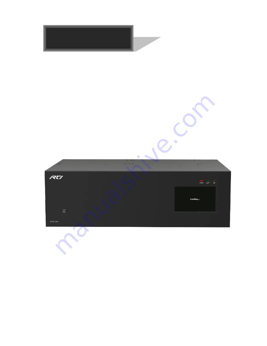
Page 9: ...mode Red when the device is powered on ACT RS232 Link indicator Off when there is no RS232 serial signal Blinking green when there is RS232 serial signal IR IR indicator Off when there is no IR signal Blinking red when the built in IR sensor receive IR signal FIRMWARE Micro USB port used for firmware update Touch Screen Touch screen for controlling this unit PWR IR ACT FW VFX 124 1 4 5 2 3 ...
Page 10: ...ol the matrix switcher or the 3rd party device connected to VFX IHT VFX OHT IR ALL IN Input port for IR control signal connect with IR receiver and work with IR emitters connected to IR OUT of far end HDBT receivers IR EYE Connect with IR receiver to control the switcher Power Port Connect to 100 240V AC outlet with power cord TCP IP TCP IP control port connect with control device e g a PC Ground ...
Page 11: ...X OHT 4K HDBT Analog Audio RS232 IR VFX IV4 VGA Analog Audio VFX OA1 MIC LINE IN MIX OUT PGM OUT 2 3 1 VFX IHM VFX OHM Single 4K seamless HDMI signal card refer to 9 2 1 for detailed specification HDMI1 4 HDCP2 2 compliant capable to transmit HDMI DVI I DVI D signal Auto detect input resolution Max resolution 4K 2K 60Hz 4 2 0 The default output resolution is 4K 2K 30Hz and it can be adjusted via c...
Page 12: ...ignal support HDCP1 4 Work with HDBT transmitter receiver to attain long distance transmission up to 70m via qualified CAT6 cable for 1080P or 40m for 4K signal Real time work status indicator yellow LED blinks once powered on green LED lights when the port is connected with HDBT devices HDBT port supports PoE Input audio source selectable via command or GUI including HDMI embedded audio default a...
Page 13: ...3 VFX IV4 4K seamless VGA signal input card refer to 9 2 3 for detailed specification Max VGA input resolutions 1920 1200p 60Hz External analog audio input for VGA video signal Work with VFX OHM VFX OHT output cards to switch video audio input signal and the video signal can be adjusted as 4K 30Hz 4 4 4 Figure 2 5 VFX IV4 Note When one PC used as input source due to some models aren t compatible w...
Page 14: ... external MIC or LINE audio input Features MIX OUT port to output MIC LINE source audio simultaneously Features PGM OUT port to output MIC LINE source audio simultaneously and then the mixed sound volume and channel can be controlled via GUI Works with VFX IHM VFX IHT VFX IV4 to output the de embedded audio Figure 2 6 VFX OA1 ...
Page 15: ...6 AUDIO MIC IN AUDIO OUT R L MIX OUT R L OUTPUT 4K Tx Rx R L IR OUT IR IN RS232 AUDIO HDBaseT OUTPUT 4K Tx Rx R L IR OUT IR IN RS232 AUDIO HDBaseT OUTPUT 4K Tx Rx R L IR OUT IR IN RS232 AUDIO HDBaseT OUTPUT 4K Tx Rx R L IR OUT IR IN RS232 AUDIO HDBaseT OUTPUT HDMI AUDIO L R 4K OUTPUT HDMI AUDIO L R 4K INPUT AUDIO L R 4K HDMI INPUT AUDIO L R 4K HDMI 4K RS232 AUDIO Tx Rx R L INPUT IR OUT IR IN HDBas...
Page 16: ...ts Step3 Connect displays to corresponding output ports Step4 Connect amplifier speaker to audio output ports Step5 Connect an IR Receiver to IR EYE to enable IR control Step6 Connect control device e g a PC to the RS232 port to enable serial control Step7 Connect control device e g a PC to the TCP IP port to enable TCP IP control Step8 Insert 100 240V AC outlet via the included power cord ...
Page 17: ...nvenient touch screen for network setting Signal Switching preset management EDID management audio setting and system information inquiry The main menu is shown as below 4 1 System Information Query Press SYSTEM INFO to enter the below menu which show product model GUI version and system update time ...
Page 18: ...rd Matrix Switcher 11 4 2 Signal Card Information Query Press CARD INFO to enter the below menu which show signal card information 4 3 Network Setting 1 Press NETWORK SETTING to enter the below menu to configure network ...
Page 19: ...Single Plug in Card Matrix Switcher 12 2 Press Modify to enter the below interface to select IP mode 3 Press Next to enter the below interface to modify IP address ...
Page 20: ...Single Plug in Card Matrix Switcher 13 4 Press Next to enter the below interface to set subnet mask 5 Press Next to enter the below interface to set default gateway ...
Page 21: ...Single Plug in Card Matrix Switcher 14 6 Press Next to enter the below interface to confirm network setting 7 Press Confirm to enter the below interface to save IP mode setting ...
Page 22: ...terface to save network setting and then press YES to confirm setting or NO to cancel 4 4 Signal Switching Press SIGNAL ROUTING to enter the below menu to switch input and output connection Once select any input signal card the corresponding outputs will highlight it in orange ...
Page 23: ...t Press INPUT OUTPUT GO Example Press 2 To switch an input to several outputs Press INPUT OUTPUT OUTPUT GO Example Press 3 To switch an input to all outputs Press INPUT ALL GO Example Press Press to cancel operations before pressing Press to return the previous signal routing setting ...
Page 24: ...s can be stored to preset 1 4 Press PRESET to enter the below menu to save recall or clear the preset Operation example 1 Press and then press to save the signal switching status on SIGNAL ROUTING menu to Preset 1 2 Press and then press to recall Preset 2 3 Press and then press to clear Preset 3 ...
Page 25: ...r features EDID management to maintain compatibility between all devices Press EDID to enter the below menu to set the EDID of input source device EDID setting operation 1 Set one output EDID to one or several input Press OUTPUT INPUT INPUT LEARN Example 1 press Example 2 press ...
Page 26: ...RN EDID Z Z 1 6 Video Resolution Audio Format 1 1920x1080P 60HZ 8 bit Stereo 2 1920x1080P 60HZ 8 bit Dolby Digital DTS 5 1 3 3840x2160P 30HZ 8 bit Stereo 4 3840x2160P 30HZ 8 bit Dolby Digital DTS 5 1 5 3840x2160P 60HZ 8 bit 4 2 0 Stereo 6 3840x2160P 60HZ 8 bit 4 2 0 Dolby Digital DTS 5 1 Example 1 press Example 2 press ...
Page 27: ...r VFX OA1 signal card When select audio signal card then volume adjuster will show on the right side of the interface Operation procedure Select one audio signal card such as Press or to switch on or off source and MIC LINE audio When switch on audio then move the scroll bar on the right to increase or decrease the volume of source and MIC LINE audio ...
Page 28: ... Select all inputs or outputs EDID Press this to enter EDID management menu Clear Press this to cancel the operations before pressing ENTER Arrow keys Up Down Left and Right and ENTER button Press Left key at any interface can enter SIGNAL ROUTING menu Press Up and Down key to select the embedded EDID in the EDID management menu Press Right key at any interface can enter EDID menu Press ENTER to c...
Page 29: ... Press Left key INPUT 06 OUTPUT 09 OUTPUT 10 OUTPUT 11 ENTER 3 To switch an input to all outputs Press Left key INPUT XX ALL ENTER Example Press Left key INPUT 06 ALL ENTER Press Clear to cancel the operations before pressing ENTER 5 3 EDID Management The IR remote can be used for learning EDID and invoking the embedded EDID 1 Set one output EDID to one or several input Press EDID Right key OUTPUT...
Page 30: ...onfirm EDID Z Z 1 6 Video Resolution Audio Format 1 1920x1080P 60HZ 8 bit Stereo 2 1920x1080P 60HZ 8 bit Dolby Digital DTS 5 1 3 3840x2160P 30HZ 8 bit Stereo 4 3840x2160P 30HZ 8 bit Dolby Digital DTS 5 1 5 3840x2160P 60HZ 8 bit 4 2 0 Stereo 6 3840x2160P 60HZ 8 bit 4 2 0 Dolby Digital DTS 5 1 Example 1 Press EDID Up Down to select the embedded EDID 1 INPUT 06 ENTER Example 2 EDID Up Down to select ...
Page 31: ...ed software 6 1 RS232 Control Software Installation Copy the control software file to the computer connected with the matrix switcher Uninstallation Delete all the control software files in corresponding file path Basic Settings Firstly connect the matrix switcher with an input device and an output device Then connect it with a computer which is installed with RS232 control software Double click t...
Page 32: ... of COM number bound rate data bit stop bit and the parity bit correctly only then will you be able to send command in Command Sending Area Communication Protocol Baud rate 9600 Data bit 8 Stop bit 1 Parity bit none Parameter Configuration area Monitoring area indicates whether the command sent works Command Sending area ...
Page 33: ... by the front panel POW STANDBY FPL Report front panel lock status FPL UNLOCKED FPL LOCKED FPL LOCK Lock front panel button FPL LOCKED FPL UNLOCK Unlock front panel button Default FPL UNLOCKED FWV Report front panel version FWV 1 0 0 FBK OFF Disable feedback message FBK OFF FBK ON Enable feedback message FBK ON CRD ALL Get all signal card type CRD XX Y Z 1 start 2 CRD CARD 3 XX card slot number i ...
Page 34: ...d Description Feedback Example UDO Cancel the previous operation UDO RAV XX AVALL Switch input XX AV to all output RAV VIDEO 02 TO OUT ALL RAV XX V Y1 Y2 Switch Input XX AV signal to output Y1 and all target output in Y2 and so on RAV VIDEO 01 TO OUT 08 RAV VIDEO 01 TO OUT 09 RAV VIDEO 01 TO OUT 10 RAV VIDEO 01 TO OUT 11 RAV VIDEO 01 TO OUT 12 RAV VIDEO 01 TO OUT 13 RAV VIDEO 01 TO OUT 14 RPT YY R...
Page 35: ...RAV VIDEO FF TO OUT ALL RAV XX AVOFF Turn off the video output XX RAV VIDEO 00 TO OUT 16 RAV XX AVON Turn on the video output XX RAV VIDEO FF TO OUT 16 6 2 3 Preset Management Command Command Description Feedback Example PST YY STO Store the current status to preset YY YY ranges from 01 to 10 PST 10 STO PST YY RCL Recall preset YY PST 06 RCL RAV VIDEO 03 TO OUT 08 RAV VIDEO 03 TO OUT 09 RAV VIDEO ...
Page 36: ...YY RE S720P Set the output resolution of output YY to 720P RES OUT 16 1280x720P60 CFG OUT YY RE S1080P Set the output resolution of output YY to 1080P RES OUT 16 1920x1080P60 CFG OUT YY RE SXGA Set the output resolution of output YY to 1024x768 60Hz RES OUT 16 1024x768P60 CFG OUT YY RE S2160P30 Set the output resolution of output YY to 3840x2160 30Hz RES OUT 12 3840x2160P30 CFG OUT YY RE SUHD Set ...
Page 37: ...G INP 07 RST 6 2 7 RS232 Pass through Control Command Command Description Feedback Example CMD ZZ XX Y Y DATA CMD Command separator ZZ 00 01 02 00 when matrix is working 01 when matrix is PWON 02 when matrix is PWOFF XX port number of HDBaseT receiver 01 32 YY buad rate 01 2400 02 4800 03 9600 04 19200 05 38400 06 57600 07 115200 DATA data to other device through RS 232 FEEDBACK feedback from othe...
Page 38: ...S232 port of this Matrix Switcher CFG INP 05 RS232M2 CFG OUT YY RS 232M1 RS232 pass through control mode 1 Control far end device from the RS232 port of this output card CFG OUT 31 RS232M1 CFG OUT YY RS 232M2 RS232 pass through control mode 2 factory default Control far end device from the RS232 port of this Matrix Switcher CFG OUT 31 RS232M2 ...
Page 39: ...thernet port of control device and TCP IP port of the matrix switcher and set same network segment for the 2 devices users are able to control the device via GUI or designed TCP IP communication software 7 1 Control Mode The matrix switcher can be controlled by PC without Ethernet access or PC s within a LAN Controlled by PC without Ethernet access Connect a computer to the TCP IP port and set its...
Page 40: ...ollow these steps to connect the devices Step1 Connect the TCP IP port of the matrix switcher to Ethernet port of PC with straight thru CAT5e 6 Step2 Set the PC s network segment to the same as the matrix switcher s Step3 Set the matrix switcher s network segment to the same as the router Step4 Set the PC s network segment to the original ones Step5 Connect the matrix switcher and PC s to the rout...
Page 41: ...trol Exampled by TCPUDP software 1 Connect a computer and the matrix switcher to the same network Open the TCPUDP software or any other TCP IP communication software and create a connection enter the IP address and port of the matrix switcher default IP 192 168 0 178 port 4001 ...
Page 42: ... After connect successfully we can enter commands to control the matrix switcher as below Here you will receive the feedback when a command is sent Enter your command here Commands are the same with RS232 commands listed in 6 2 RS232 Commands ...
Page 43: ...the browser PCs running Windows XP system may occur issues in finding UPnP icon follow these steps to switch on UPnP protocol Add UPnP component go to Control Panel double click Add Delete Programs double click Add Delete windows component tick UPnP click Next click OK Enable Windows Firewall go to Control Panel double click Windows Firewall click Others tick UPnP framework Enable UPnP auto starti...
Page 44: ... Password user default setting changeable via GUI It will enter scene management interface left after log in which provides direct scene switch The chart below illustrates the main structure of GUI interfaces The GUI system can be divided into Switch Control and System Setting menu but log in as user will only access Switch Control Click at the left bottom corner to enter Switch Control menu Click...
Page 45: ...e interface Select a scene and then click Load can invoke the selected scene Click cancel to cancel the current operation 7 3 2 Signal Switching The button matrix displays every possible connection between every input and output users can carry on the connections by clicking corresponding button ...
Page 46: ...UT ports in needed you only need to click All Step3 Choose a scene that you want to save Step4 Click Confirm to save the setting or Click Clear to clear set up 7 3 3 Output Resolution Selection The output resolution can be selected VFX OHM VFX OHT support 4K 2K 60Hz 4K 2K 30Hz 1024 768 60Hz 1920 1080p 60Hz 1280 720 60Hz VFX OA1 Unavailable ...
Page 47: ...Matrix Switcher 40 7 3 4 VGA Signal Format Setting The VGA signal format of VFX IV4 can be set as VGA YPBPR or CVBS 7 3 5 Network Setting DHCP automatically assign IP by router or static IP manually set IP can be selected ...
Page 48: ...ut Setting Enable or disable the audio input port of VFX IHM VFX IHT and VFX IV4 VFX OA1 Unavailable 7 3 7 Audio Output Setting Enable or disable the audio output port for 1080p signal cards Note If the audio output can t be set its button will turns gray ...
Page 49: ...is only used for controlling the PGM port of VFX OA1 signal card It supports MIC LINE input selection and stereo mono audio output selection The mixed audio volume can be adjusted 7 3 9 Product Name and Model Setting The product name and model can be renamed max at 16 numbers letters ...
Page 50: ...tcher 43 7 3 10 Signal Channels Label Setting The input and output channels label can be reset max at 7 numbers letters Chinese characters 7 3 11 Scene Name Setting The scene can be rename max at 7 numbers letters Chinese characters ...
Page 51: ... 3 12 Firmware Version Query Click the corresponding button to get the firmware version of device or signal card 7 3 13 Display Resolution and Brand Query Click the corresponding button to get the display resolution and brand from output port ...
Page 52: ...management interface enable one all input s capture and learn the EDID data from one output One input learns EDID from one output Output Input Confirm All inputs learn EDID from one output Output To All Input Undo the previous input Click Cancel 7 3 15 Password Setting ...
Page 53: ...bsite 192 168 0 178 100 Default changeable via GUI in your browser Enter correct username and password same with GUI name and password to log in the WebServer Here is the main configuration interface of the WebServer In this interface you can Change website display language Modify network settings Go to Internet Settings WAN Upgrade TCP IP module Go to Administration Upload Program Select program ...
Page 54: ...the USB ports of the switcher and the PC via USB cable Step3 Double click the update software icon see as below It will enter the upgrade interface shown as below Step4 Click Connect USB Step5 Click Open to load the upgrade file then click Updata to start firmware upgrading Note To ensure available control the COM number of the PC should be 1 9 If the update progress bar can t go on please cut off...
Page 55: ...x 320mm 9 2 Signal Cards 9 2 1 VFX IHM VFX OHM VFX IHM Input 1 HDMI 1 Analog audio Input Connector 1 19 pin Type A Female HDMI 1 3 pin pluggable terminal block Power Consumption 4w max VFX OHM Output 1 HDMI 1 Analog audio Output Connector 1 19 pin Type A Female HDMI 1 3 pin pluggable terminal block Power Consumption 1 5w max General Switching Speed 100ns Standard HDMI1 4 HDCP2 2 Operation Temperat...
Page 56: ...alog audio 1 RS232 1 IR IN 1 IR OUT Output Connector 1 Female RJ45 2 3 pin pluggable terminal block 2 3 5mm mini jack Power Consumption 17w max General Transmission Distance 1080p 70m Cat6 4Kx2K 40m Cat6 Switching Speed 100ns Operation Temperature 0 40 Storage Temperature 10 55 Relative Humidity 10 90 Standard HDMI2 0 HDCP2 2 Audio PCM EDID Supports EDID Management Output Resolution Auto 4Kx2K 60H...
Page 57: ...dB 20Hz 20KHz General Power Consumption 2w max Switching Speed 100ns Operation Temperature 0 40 Storage Temperature 10 55 Relative Humidity 10 90 9 2 4 VFX OA1 Input 1 MIC LINE IN Input Connector 1 3 pin pluggable terminal block Output 1 MIX OUT 1 PGM OUT Output Connector 2 3 pin pluggable terminal block General Signal Format PCM Power Consumption 5W Frequency Response 20Hz 20KHz 0 5dB CMRR 85dB 2...
Page 58: ...Single Plug in Card Matrix Switcher 51 10 Panel Drawing PWR IR ACT FW VFX 124 437 mm 132 mm 23 mm ...
Page 59: ...or quality of the connecting cable Change for another cable of good quality Poor contact at the input output end Reconnect the devices and make sure they re well contacted Cannot control the device via front panel buttons Front panel buttons are locked Send FPL UNLOCK to unlock Cannot control the matrix switcher by control device e g a PC through RS232 port Wrong RS232 communication parameters Mak...
Page 60: ...ut your RTI product please contact RTI Technical Support for assistance see the Contacting RTI section of this guide for contact details RTI provides technical support by telephone fax or e mail For the highest quality service please have the following information ready or provide it in your fax or e mail Your Name Company Name Telephone Number E mail Address Product model and serial number if app...
Page 61: ......
Page 62: ......
Page 63: ......
Page 64: ...Remote Technologies Incorporated 5775 12th Avenue East Suite 180 Shakopee MN 55379 Tel 952 253 3100 Fax 952 253 3131 www rticorp com ...