background image

R60-AL User Manual

Rtelligent.cn

-

6

-

3.2.1 PUL

DIR(IN1

IN2) port

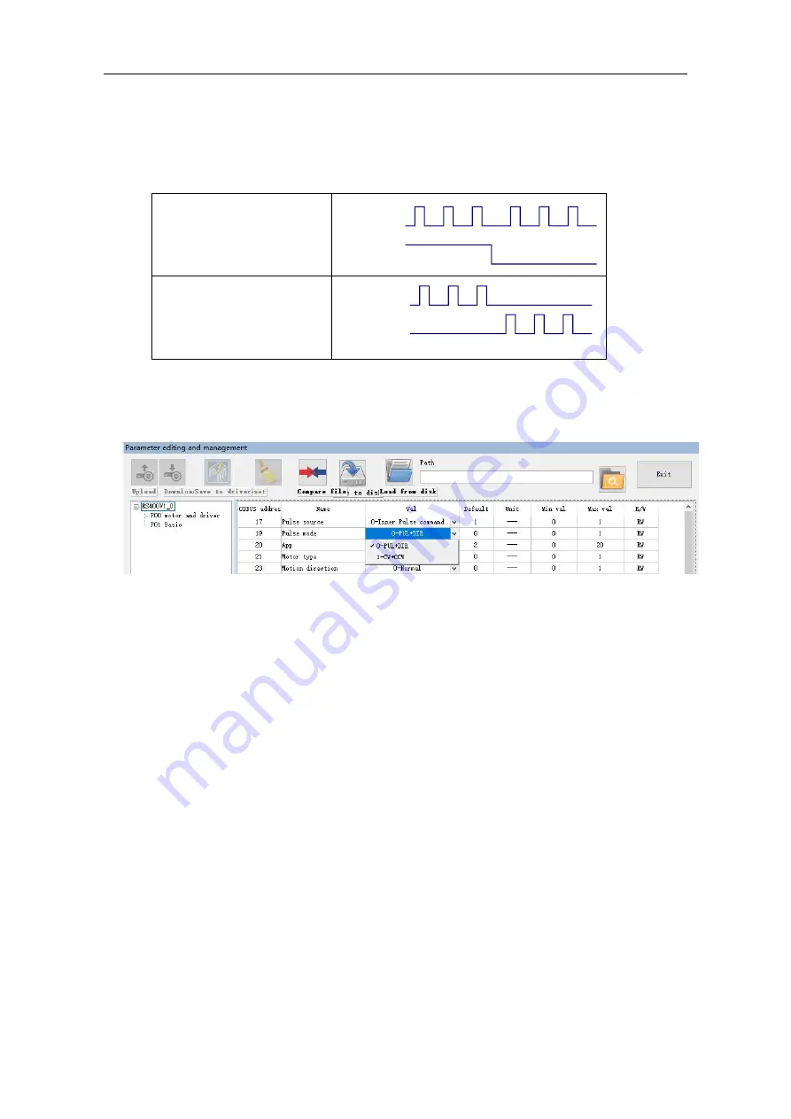
When working in external pulse command mode by default, R60-AL can receive two pulse
command signals: PUL + DIR, CW + CCW.

External pulse command form through debugging software

脉冲

&

方向(

PUL +

DIR

PUL

DIR

Forward

Reverse

双脉冲(

CW +CCW

PUL

DIR

Forward

Reverse

Summary of Contents for R60-AL

Page 1: ...l connection 5 3 2 1 PUL DIR port connection for pulse instructions 6 3 2 2 ENA port used to enable or disable 7 3 2 3 ALM port for alarm output 7 3 3 USB port 7 4 The setting of DIP switches and oper...

Page 2: ...R60 AL User Manual Rtelligent cn 2 8 1 2 Jog control mode 13 8 2 IO control start stop direction 14 8 3 IO control forward reverse 14 9 Common Faults and Troubleshooting 15...

Page 3: ...motor Phase loss alarm function Digital IO port 3 optically isolated digital signal inputs high level can directly receive 24V DC level 1 optically isolated digital signal output maximum withstand vol...

Page 4: ...A Power supply V Positive pole of power supply Pls do not connect reverse the power V Negative pole of power supply 3 1 1 Power input The driver s working power is DC power and the input voltage rang...

Page 5: ...er motor also retains the characteristics of the generator when it is working During deceleration the kinetic energy accumulated by the load will be converted into electrical energy and superimposed o...

Page 6: ...R IN1 IN2 port When working in external pulse command mode by default R60 AL can receive two pulse command signals PUL DIR CW CCW External pulse command form through debugging software PUL DIR PUL DIR...

Page 7: ...motor is in an error state the enable is automatically disconnected The level logic of the enable signal can be set to the opposite At the same time this port can be multiplexed with other functions l...

Page 8: ...andby SW4 ON as long as the driver is in the enabled state the current remains at the set current SW4 OFF after the driver stops receiving pulses for a certain period of time it enters the standby sta...

Page 9: ...ming at the resonance problem of two phase stepper motors in the low speed region R60 AL uses a harmonic algorithm to effectively reduce the resonance of the motor Generally the first resonance point...

Page 10: ...e of the motor will be significantly reduced The third step is to let the motor run at the second resonance point and maintain the current speed The fourth step is to adjust the amplitude and phase of...

Page 11: ...al pulse command mode the PUL and DIR ports are used as IO input signals The IO functions need to be set through the debugging software RStepper Configurator As shown below 8 1 Communication control m...

Page 12: ...g is required you can write value 6 deceleration stop deceleration is set value of register 71 value 5 emergency stop stop deceleration is set value of register 78 into register Note When the motor is...

Page 13: ...ard rotation and 4 continuous reverse rotation to register 18 for details of this register please refer to Drive Control Mode Setting 17 to 23 in register 18 5 During operation if stopping is required...

Page 14: ...motor One of the IN terminals is used to control the start stop of the motor and one IN terminal is used to control the running direction of the motor The specific settings are as follows 1 Command w...

Page 15: ...e direction with software The motor cable is disconnected Check the connection The motor has only one direction Pulse mode error or DIR port damaged Alarm indicator is on The motor connection is wrong...

Reviews: