R.T.A. s.r.l. – ADW_ME05 – 09/21
10/22
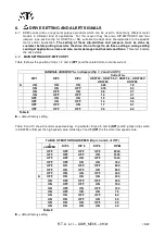
4.1 - LOGIC INPUT AND OUTPUT SIGNALS
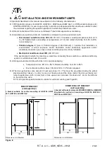
An input is ON when at its terminals is present a voltage within the following limits:
Vin-
MIN
= 5 Volt, Vin-
MAX
= 24 Volt
For each input signal, correspondent terminals numbers of connector AM3 (C2 in ADW 94/96) are indicated.
All logic input signals are optically insulated (respect to internal power circuit). Analog input and STEP output
are not optically insulated but are referred to A-GND (Pin 8 of AM3 / C2 connector).
Note: Driving an input with a slow signal (i.e relays) or with variable delay (i.e PLC output) can give
precision problem or, worse, make the board do not work at all. If you have this type of signal,
contact R.T.A.
1
COMMON OF INPUTS
.
2
CURRENT OFF INPUT:
When this signal is ON drive is active. When it is OFF drive is inhibited, thus
motor current (and so holding torque) is turned to zero.
With jumper CO this input is always ON
(drive is always active).
3
DIRECTION INPUT:
With this signal ON motor rotation direction is opposite to the one obtained with
input OFF. This signal has to be valid at least 100 µsec. before START or STOP signals transition and
has to stay in this state for at least 100 µsec. after last START or STOP signals transition. This input is
not active in CW/CCW operation mode.
4
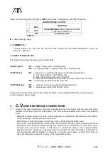
START
: Start signal function is showed in TABLE 3, depending on the set of drive operation mode:
PIN 4 (START) OPERATION MODE
DRIVE OPERATION MODE
INPUT SIGNAL
RUN
ON (Level Sensitive)
Run Start
OFF
Run Stop
CW/CCW
ON (Level Sensitive)
CCW Enable
OFF
Not Used
START - STOP
ON (Positive Edge Sensitive)
Motor Start
OFF
Not Used
LIMIT SWITCH
ON (Negative Edge Sensitive)
CCW Stop
OFF
Not Used
Table 3
When the motor stops and after adjustment it keeps the load blocked with the torque at 50% of the set value
(automatic current reduction). The maximum delay at enabling or disabling is lower than 1.5 ms.
Note:
In CW/CCW mode the motor stops when Pin 4 logic level is equal to Pin 5 logic level.
5
STOP
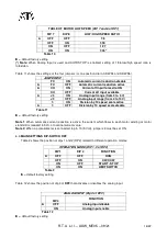
: Stop signal function is showed in TABLE 4:
PIN 5 (STOP) OPERATION MODE
DRIVE OPERATION MODE
INPUT SIGNAL
RUN
ON (Level Sensitive)
Not Used
OFF
Not Used
CW/CCW
ON (Level Sensitive)
CW Enable
OFF
Not Used
START - STOP
ON (Positive Edge Sensitive)
Motor Stop
OFF
Not Used
LIMIT SWITCH
ON (Negative Edge Sensitive)
CW Stop
OFF
Not Used
Table 4
Note:
In CW/CCW mode the motor stops when pin 4 logic level is equal to pin 5 logic level.


