DT2350 2-Channel Strain Gauge
Load Cell Data Logger Manual
ELM0099A
RST Instruments Ltd.
Page 4
F
IGURE
3-2
L
OOSEN THE CABLE GLAND USING THE CABLE GLAND NUT WRENCH
2
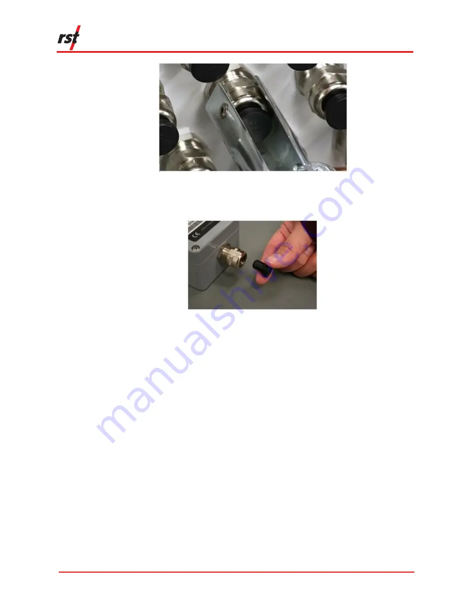
Remove the black cable plug from the cable gland. Refer to Figure 3-3.
F
IGURE
3-3
R
EMOVE THE CABLE PLUG FROM THE CABLE GLAND
3
Loosen the 4 Phillips screws on the top of the logger. Lift the cover off.
4
Insert the sensor cable with stripped wire ends through the cable glands and into
the logger. Ensure the cable sheathes are inside the enclosure.
5
Connect the leads. Refer to Figure 3-4 and Table 3-1.


